-----
-
--
TIIE
FUEL
SYSTEM
B
The
filter can be removed by unscrewing
the
hexagon
plug at tile
bottom
of
the
pump, when it can becleaned
in fuel with a stiff brush.
Never
use rag
to
dean
a
filter.
Section
0.8
THE CARBURETTERS
Two S.U.
carburetters
of
the
controllable
jet
type,
complete
with
an air cleaner,
are
fitted.
Each
carburetcer
is provided
with
a
damper,
and
this
consists of a
plunger
and
non-return
valve attached
to
the
oil cap
nut.
The plunger works in
the
hollow
piston rod, which should be partly filled with light
engine oil
to
Ref. F (page P.2).
The
object of
the
damper
is
to
provide a slightly enriched
mixture
on
acceleration.
Seetion
B.D
SETTING THE
TWIN
CARBURETIERS
When
setting
the
carburetters
the
first thl ng
to
do is
to
remove
the
air cleaner and intake elbow and
then
make
quite
sure
the
carbu
retter
pistons are free
and
that
the
jets
are
correctly
centred
(explained
under
Section B.
II)
. It is also necessary
to
make
sure
that
the
mlxture and
throttle
I
nterconnect
ion adjust-
ing
screw
is
dear
of
the
rocking lever anvil
when
the
mixture
control
knob
on
the
instrument
panel is
pushed right home,
Next,
one
of
the
clarnpl ng bolts on
either
of
the
two
flexible couplings on
the
throttle
interconnecting
spindle should be undone and
the
jet
lever Inter-
connecting rod disconnected at e
ither
of
the
jet
levers.
This is
done
by removing
the
clevis pin attaching
the
control
to
one of
the
jet
levers.
_---
Float-chamber
'-------------Jet
head
il4------0
il cap nut
__
-Float
_
...
----
Float depressing
plunger
.;--------
Piston rod
~~---
Float needle
......
~---Oil
dashpct
<4§--------
Jet adjusting lever
Tapered
i
e t
_
~
:--
__
needle
Jet
orifice-~----
Piston
---
_____
Suction
disc---_.
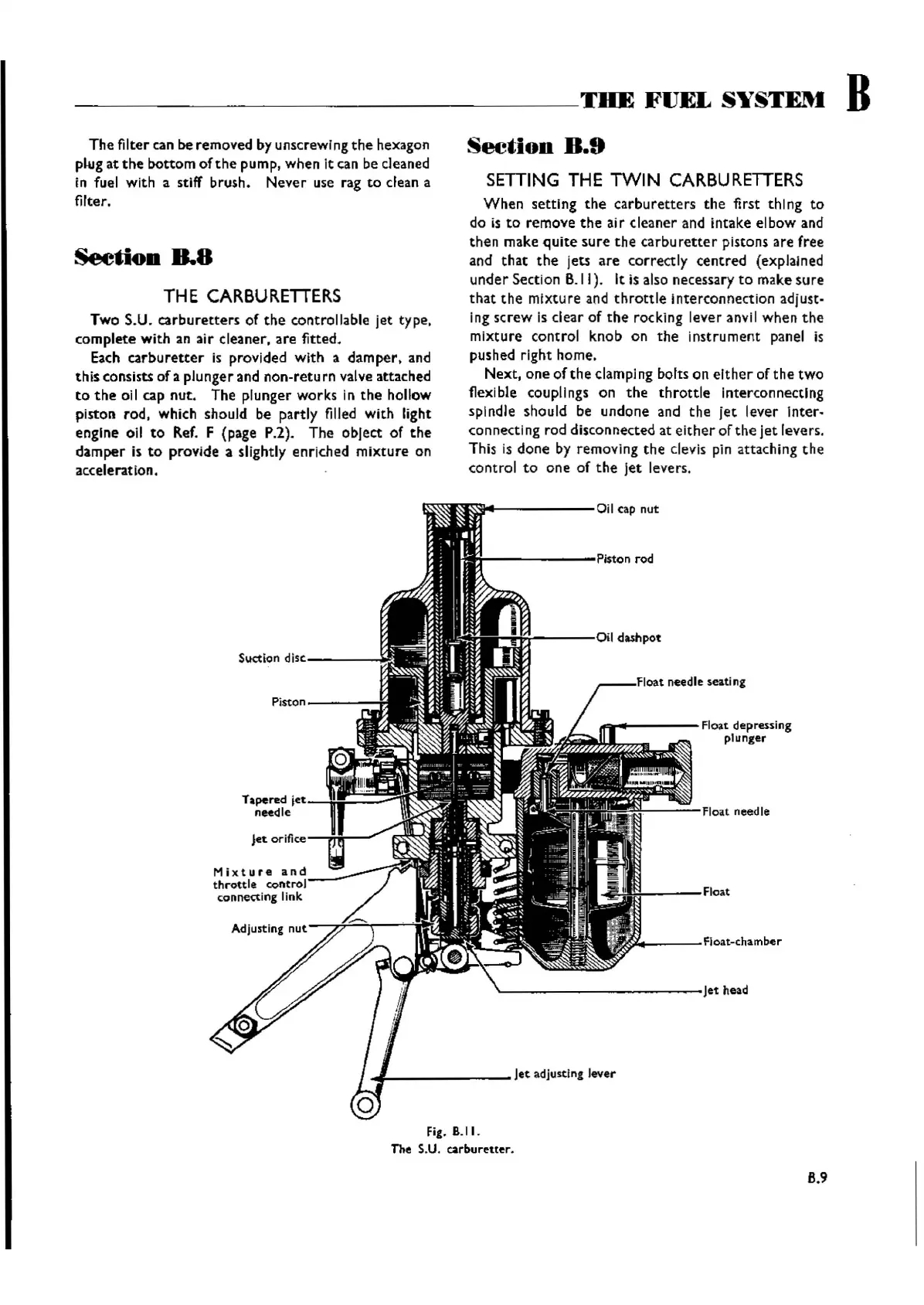
Fig. 6.11.
The S.U.
carburetter,
B.9
Wishvilles Classic
Automobile Library

 Loading...


