the
wiring for
the
fault and replace with
the
spare fuse
provided.
It Is also possible
that
the
performance of a horn
may be upset by
the
fixing bolt working loose,
or
by
some
component
near
the
horn becoming loose. If
after carrying
out
the
above examination
the
trouble
is not rectified.
the
horn may need adjustment,
but
this should
not
be necessary until
the
horns have been
in
service for a long period.
Adjustment does not
alter
the
pitch of
the
note, it
merely takes up wear of moving parts.
When
adjusting
the
horns, short-circuit
the
fuse, otherwise it is liable
to
blow. Again, if
the
horns do not sound on adjust-
ment,
release
the
push instantly.
ADJUSTiNG NUT
LOCI< NUT
Fla. N.20.
The Lucasmodel WT614 wlndtol1e horn with
its
cover
removed
to
ihow
ttle adjustment provided
to
com-
pemate for wear.
When
making adjustments
to
a horn. always dis-
connect
the
supply lead of
the
other
horn, taking care
to
ensure
that
It does not come into contact with any
part
of
the
chassis and so
cause
a
short
circuit.
Adjustment
Remove
the
horn cover after withdrawing
the
fiXing
screw and detach
the
cover securing bracket by
springing It from
its flxtng,
Slacken
the
locknut on
the
fixed contact and
rotate
the
adjustlng nut until
the
contacts are Iust separated
(indicated by horns failing
to
sound). Turn
the
adjust-
ing nut haifa
turn
in
the
opposite direction and secure
in this position
by tightening
the
locknut. Finalty,
if
the
note is stilt unsatisfactory. do not dismantle
the
horn
but
return
It
to
a LucasService Depot
or
Service
Agent
(or
examination.
M.G. Midaet (Serles
"TD
").
luue
2
(E)
79345-1/53
See.lon
N.15
THE
FUSES
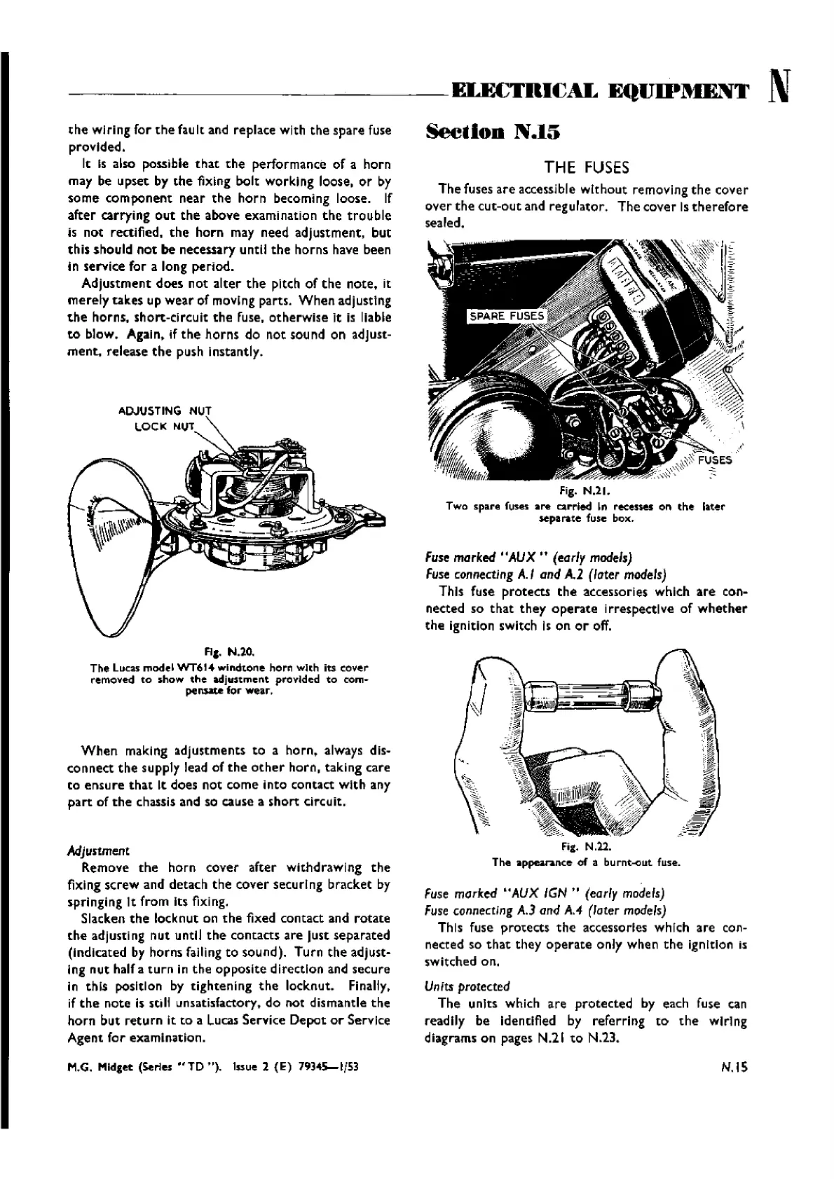
The fuses
are
accessible
without
removing
the
cover
over
the
cut-out
and regulator. The cover Is
therefore
sealed.
!!ii(
Fig.
N.ll.
Two spare fuses
are
carried In recene5 on
the
later
sepa
rate fuse box.
Fuse marked "AUX
It
(early
models)
Fuse
connecting
A.I and
A.2
(later
models)
This fuse protects
the
accessories which
are
con-
nected so
that
they
operate
irrespective
of
whether
the
ignition switch Is on
or
off.
Fuse
marked "AUX
IGN
..
(early
models)
Fuse
connecting A.3 and A,4 (later
models)
This (use protects
the
accessories which are con-
nected so
that
they
operate
only when
the
ignition is
switched on.
Units protected
The unlts which are
protected
by each fuse can
readily be identified by referring
to
the
wiring
diagrams on pages N.21
to
N.23.
N.IS
Wishvilles Classic
Automobile Library

 Loading...


