B
THE
FUEL
SYSTEM
~
~
Section
B.2
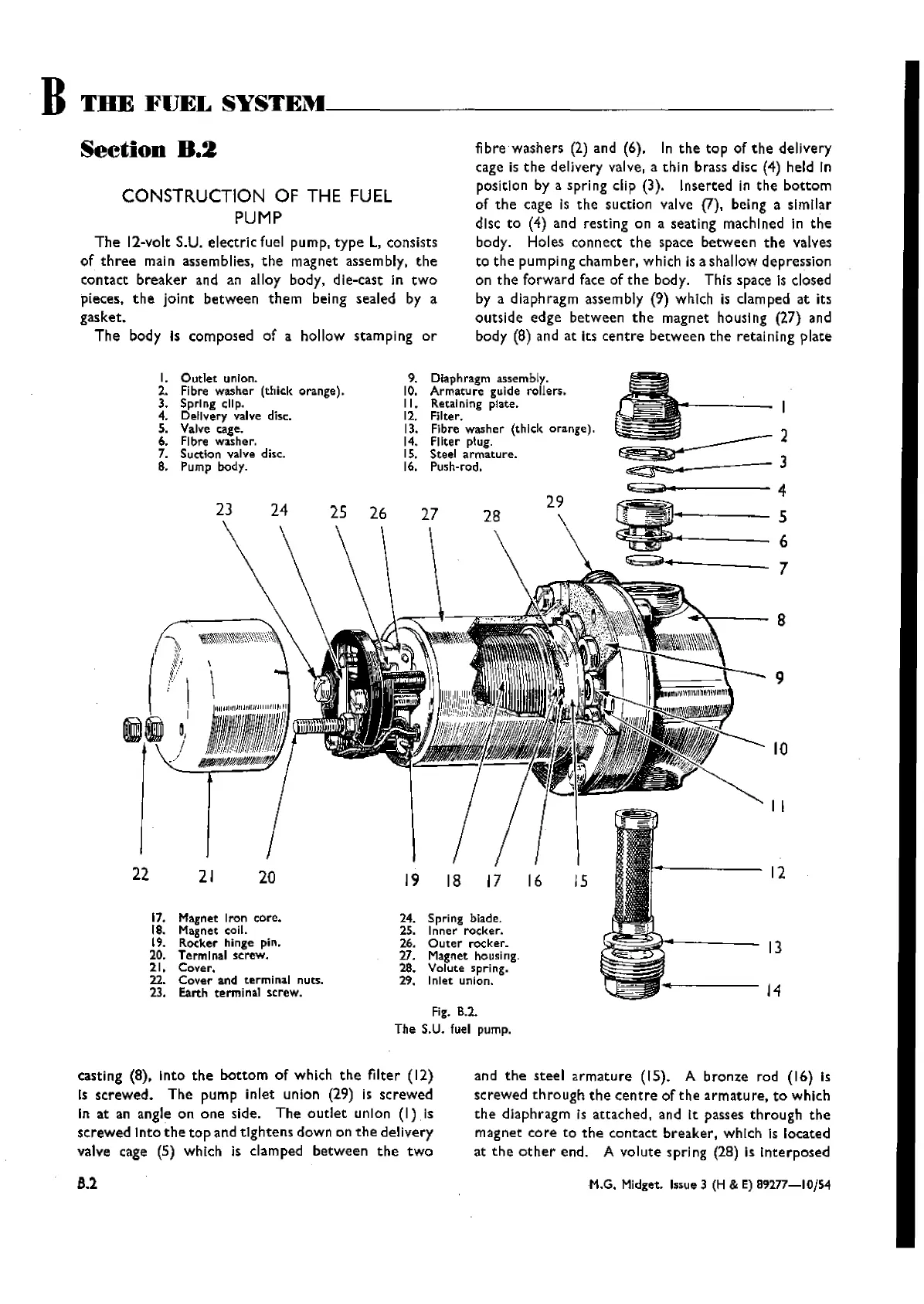
CONSTRUCTION OF THE FUEL
PUMP
The
12-volt S.U.
electric
fuel pump,
type
L, consists
of
three
main assemblies,
the
magnet assembly.
the
contact
breaker
and an alloy body, die-cast In
two
pieces.
the
joint
between
them
being sealed by a
gasket.
The
body Is composed
of
a hollow stamping
or
f
bre
washers
(2) and (6). In
the
top
of
the
delivery
cage is
the
delivery valve, a thi n brass disc (4) held In
position by a spring clip (3). Inserted in
the
bottom
of
the
cage Is
the
suction valve (7), being a similar
disc
to
(4) and resting on a seating rnachlned In
the
body. Holes
connect
the
space
between
the
valves
to
the
pumping
chamber.
which Is a shallow
depression
on
the
forward face of
the
body. This space Is closed
by a diaphragm assembly (9) which is clamped
at
its
outside
edge
between
the
magnet housing (27) and
body (8) and
at
Its
centre
between
the
retaining
plate
and
the
steel
armature
(IS). A
bronze
rod (16) Is
screwed
th rough
the
centre
of
the
arrnatureo
to
which
the
diaphragm Is
attached,
and It passes
through
the
magnet
core
to
the
contact
breaker,
which Is located
at
the
other
end. A
volute
spring (28) is
Interposed
M.G. Midget. Issue 3 (H & E)
892n-IOjS4
8
9
10
II
13
-----12
29
9. Diaphragm assembly.
10. Armature guide rollers.
II.
Retaining plate.
12. Filter.
13. FIbre washer (tilick orange).
14. Filter plug.
I
S. Steel armature.
16. Push-rod.
I.
Outlet
union.
2. Fibre
washer (thick orange).
3. Spring clip.
4. Delivery valve disc.
S. Valve cage.
6. Fibre
washer.
7. SuctIon valve disc.
8. Pump body.
22
21
20
19
18
17
16
15
17. Magnet Iron core.
24.
Spring blade.
18. Magnet coil.
25.
Inner rocker.
19.
Rocker hinge pin.
26.
Outer
rocker,
20.
Terminal screw.
27. Magnet housing.
21.
Cover.
28.
Volute spring.
22.
Cover
and terminal nuts.
29. Inlet union.
'"
23. Earth terminal screw.
Fig. 8.2.
The S.U. fuel pump.
castl ng (8), I
nto
the
bottom
of
wh ich
the
filte r (12)
Is
screwed.
The
pump inlet union (29) is
screwed
In at an angle on
one
side.
The
outlet
unIon
(I)
Is
screwed
Into
the
top
and
tightens
down on
the
delivery
valve cage (5)
which is
damped
between
the
two
8.2
Wishvilles Classic
Automobile Library

 Loading...


