~-----,------------_THE
ENGINE
A
SeetioD
A.29
GRINDING
AND
TESTING THE VALVES
AND
THEIR SEATINGS
Each valve
must
be cleaned
thoroughly
and carefully
examined
for
pitting. Valves in a
pitted
condition
should be refaced
with
a suitable
grinder
or
alternatively replaced
with
new
valves.
If
the
valve
seats
show
slgns
of
plttlng
or
uneve nness,
they
should
be
trued
by
the
use
of
a suitable
grinder
or
a special
cutter
such as Tool
No.
301075(Section
Q).
When
using a
cutter,
care should be exercised
to
remove
only
as little metal as is necessary
to
ensure
a
true
surface.
fiB.
A.D.
Uneven valve
seats
an
be
trued
with
a special
cutter.
All valves,
when
fitted
at
the
factory,
are
numbered
on
their
heads from I
to
8. and should be replaced in
the
correspondtng valve ports,
No.
I valve being fitted
to
the
port
nearest
the
front
of
the
engi ne.
When
replacement
valves
are
fitted.
th eyshould be n
umbered
to
Identify
the
port
to
which
they
belong.
The
valve face should be smeared lightly
with
fine
or
medium
grade
carborundum
paste, and
then
ground
to
In
seat, using
the
suction
grinder.
Part
No.
66893.
Avoid
the
use of excessive
quantities
of
grinding
paste;
see
that
it remains In
the
region
of
the
valve
seating only and does
not
reach
the
working
surfaces
of
the
engine. A light coli spring placed
under
the
valve head will assist considerably in
the
process
of
grinding.
The
valve should be lapped
to
its
seat
with
a semi-rotary
motion
and occasionally allowed
to
rise
by
the
pressure of
the
light coil spring. ThIs assists
in
spreading
the
paste evenly
over
the
valve face and
M.G. Mid,et. Issue 5 (H & E) 93692-5/55
seat. It Is necessary
to
carry
out
the
grinding
opera-
tion until a dull, even
matt
surface.
free
from blemish.
Is prod
uced
on
the
valve
seat
and face. If
the
valve
seat, which Is at 30°, Is found
to
be wide, it should be
reduced
with a 15°
cutter
to a
width
of
2 mrn, (,080 ln.)
for
the
exhaust
and
1·1
mm. (·043 In.] for
the
inlet
seats.
On
completion.
the
valve seats and
ports
should be
cleaned
thoroughly
with
paraffin-soaked rag,
dried,
and
then
thoroughly
cleaned by
compressed
air.
The
valves should be washed in paraffin
(kerosene),
and all
traces
of
grInding
paste
removed.
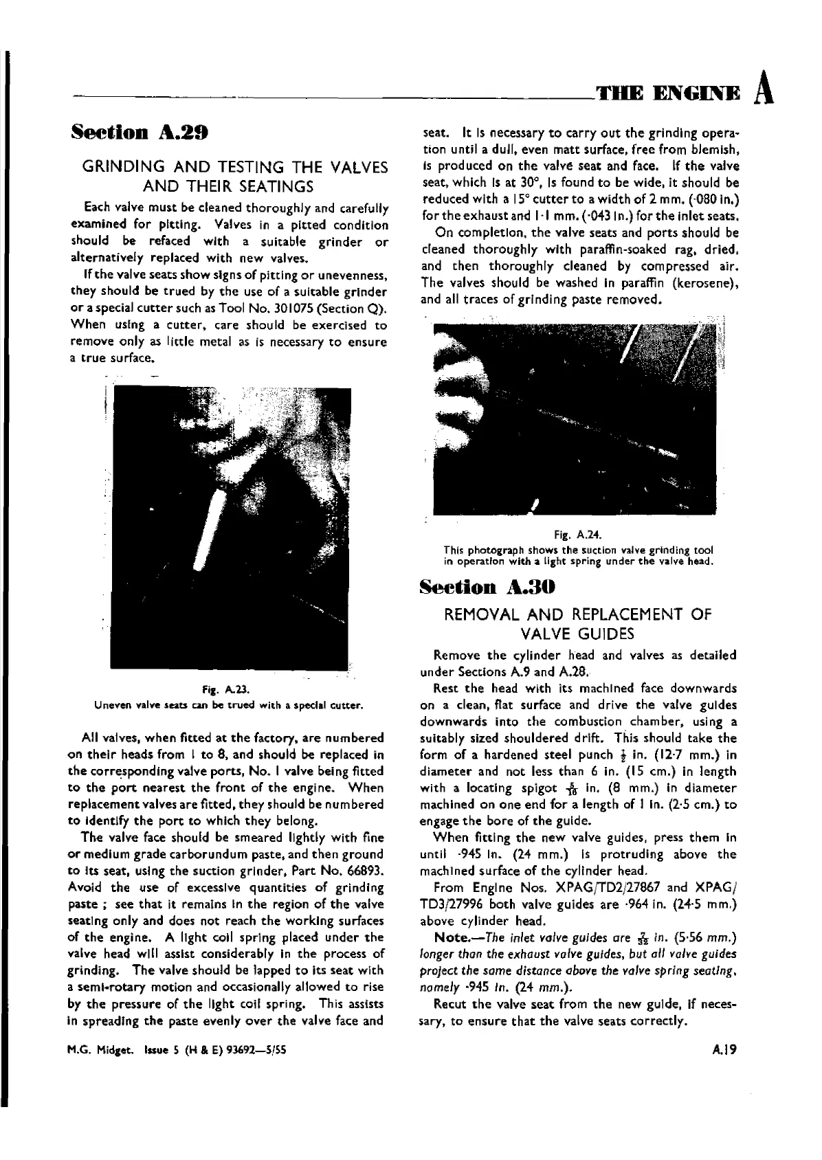
fig. A.24.
This
photograph
shows
the
suction
v<l.lve
grinding tool
in
operatfon
with
a light
spring
under
the
valve head.
SeetiOD
A.3D
REMOVAL
AND
REPLACEMENT OF
VALVE GUIDES
Remove
the
cylinder
head and valves as
detailed
under
Sections A.9 and
A.2B.
Rest
the
head
with
its machined face
downwards
on a clean. flat surface and drive
the
valve guides
downwards
into
the
combustion
chamber.
using a
suitably sized
shouldered
drift. This should
take
the
form
of
a
hardened
steel
punch i in.
(12·7
mm.) in
diameter
and
not
less
than
6 in. (15
cm.)
in
length
with a locating
spigot
-.&-
in. (8 mm.) In
diameter
machined on
one
end
for
a length of I in. (2·5
cm.)
to
engage
the
bore
of
the
gulde.
When
fitting
the
new
valve guides, press
them
in
until
·945 In. (24 mm.) is
protruding
above
the
machIned surface
of
the
cylinder head.
From Engine Nos. XPAG;TD2J27867 and XPAG/
TD3/27996 both valve guides
are
·964 in. (24·5 mm.)
above
cylinder
head.
Note.-The
inlet valve guides are nin. (5·56 mm.)
longer
than the exhaust valve guides, but all valve guides
project
the same distance
above
the valve spring seating.
namely
·945 In. (24 mm.).
Recut
the
valve
seat
from
the
new guide, if neces-
sary,
to
ensure
that
the
valve seats
correctly.
A.19
Wishvilles Classic
Automobile Library

 Loading...


