--- -- --
--
-- -
TDE
PROPELLER
SHAFT
G
place in
the
yoke
cross-holes.
rendering
them
oval.
the
yokes
must
be
renewed.
In case of
wear
in
the
cross-
holes in
the
fixed yoke. which is
part
of
the
tubular
shaft assembly, it should normally be replaced by a
complete
tubular
shaft assembly.
Only
in
the
case
of
emergency
should any
attempt
be made
to
renew
this
yoke.
Seetion
G.6
REASSEMBLING
THE
PROPELLER.
SHAFT
See
that
all
the
drilled holes in
the
journals are
thoroughly
cleaned
out
and free from grease.
Assemble
the
needle rollers In
the
bearing races and
Fig.
GA
When
dismantling
the
universal joint it
is permissible
to
tap
out
the
bear
ings
witll a small-diameter rod from tile
inside as
shown,
provided
care
is taken
not to damage the
roller
race.
fill with grease. Should dffflculty be
experienced
in
retaining
the
rollers
under
control.
smear
the
walls
of
the
races with
petroleum
jelly to retain
the
needle
rollers
In position while assembling.
Insert
the
spider
in
the
flange yoke.
ensuring
that
the
lubricator
boss
is
fitted
away
from
the
yoke.
Using a soft-nosed drift.
about
'*
in. (,8 mm.) smaller
in
diameter
than
the
hole in
the
yoke.
tap the
bearing
into position. It is essential
that
the
bearing races
are
a light
drive
fit In
the
yoke
trunnions.
Repeat
this
operation
for
the
other
three
bearings. Replace
the
circlips and be
sure
that
these
are
firmly located in
their
grooves. If
the
joint
appears to bind.
tap
lightly
....
.....
...
..t-...... .
-' . '-
....
~
,
.
--..;..--'-'--
-
-
.
,
~
- . . . . .
' ' "/ .' : .
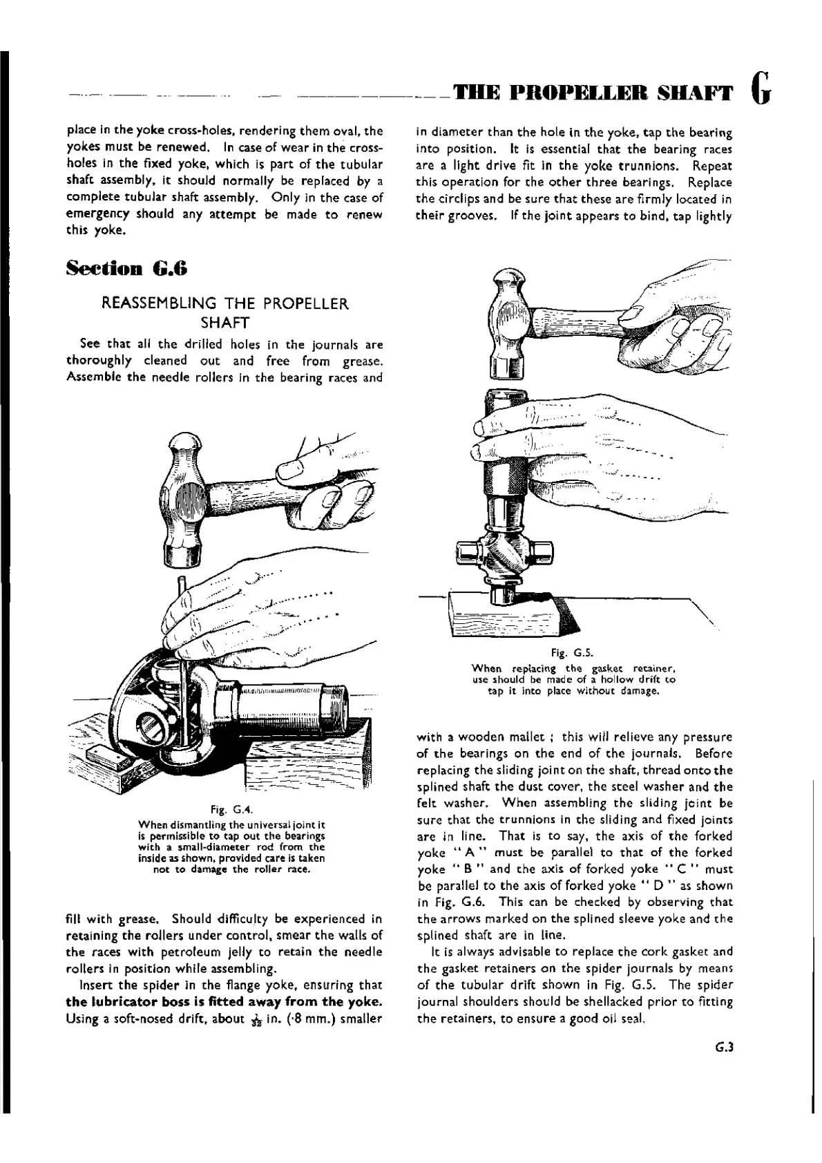
Fig. G.5.
When
replacing
the
gasket
reuiner.
use should be made of a hollow drift
to
tap
It Into place w
ithout
damage.
with a
wooden
mallet;
this will relieve any
pressure
of
the
bearings on
the
end
of
the
journals. Before
replaci ng
the
sliding jolnt on
the
shaft,
thread
onto
the
splined shaft
the
dust
cover,
the
steel
washer
and
the
felt washer.
When
assembling
the
sliding
jclnt
be
sure
that
the
trunn
ions in
the
sliding and fixed joints
are
in line.
That
is to say,
the
axis of
the
forked
yoke
"A"
must
be parallel to
that
of
the
forked
yoke"
B " and
the
axis of for ked
yoke"
C ..
must
be parallel to
the
axis of forked
yoke"
D " as shown
in Fig. G.6. This can be checked by observing
that
the
arrows
marked on
the
spllned sleeve yoke and
the
splined shaft
are
in line.
It is always advisable
to
replace
the
cork
gasket and
th e
gasket
ret
ainers on
the
spider
journ
als by means
of
the
tubular
drift
shown
in Fig. G.5. The
spider
journal
shoulders
should be shellacked
prior
to fitting
the
retainers, to
ensure
a
good
oil seal.
G.3
Wishvilles Classic
Automobile Library

 Loading...


