A
THE
ENGINE----------------~-~
to
reassemble
the
main bearing shells
to
the
correct
bearings. 011 all
parts
with
clean oil
before
assembly.
Seetion
1\.34
REGRINDING THE CRANKSHAFT
If
the
crankshaft
journals
are
found
to
be
worn,
scored
or
oval.
they
must
be
reground
undersize
or
alternatively
the
engine
must
be
fitted
with
a
replacement
crankshaft.
The
table
on page A.21 gives details
of
the
various
sizes available
for
regrindIng
to
ensure
the
supply
of
bearings
to
match.
On
XPEG engi nes
the
crankshaft
cannot
be
reground
but
may be exchanged
for
a
new
one
(Part
No.
168557),
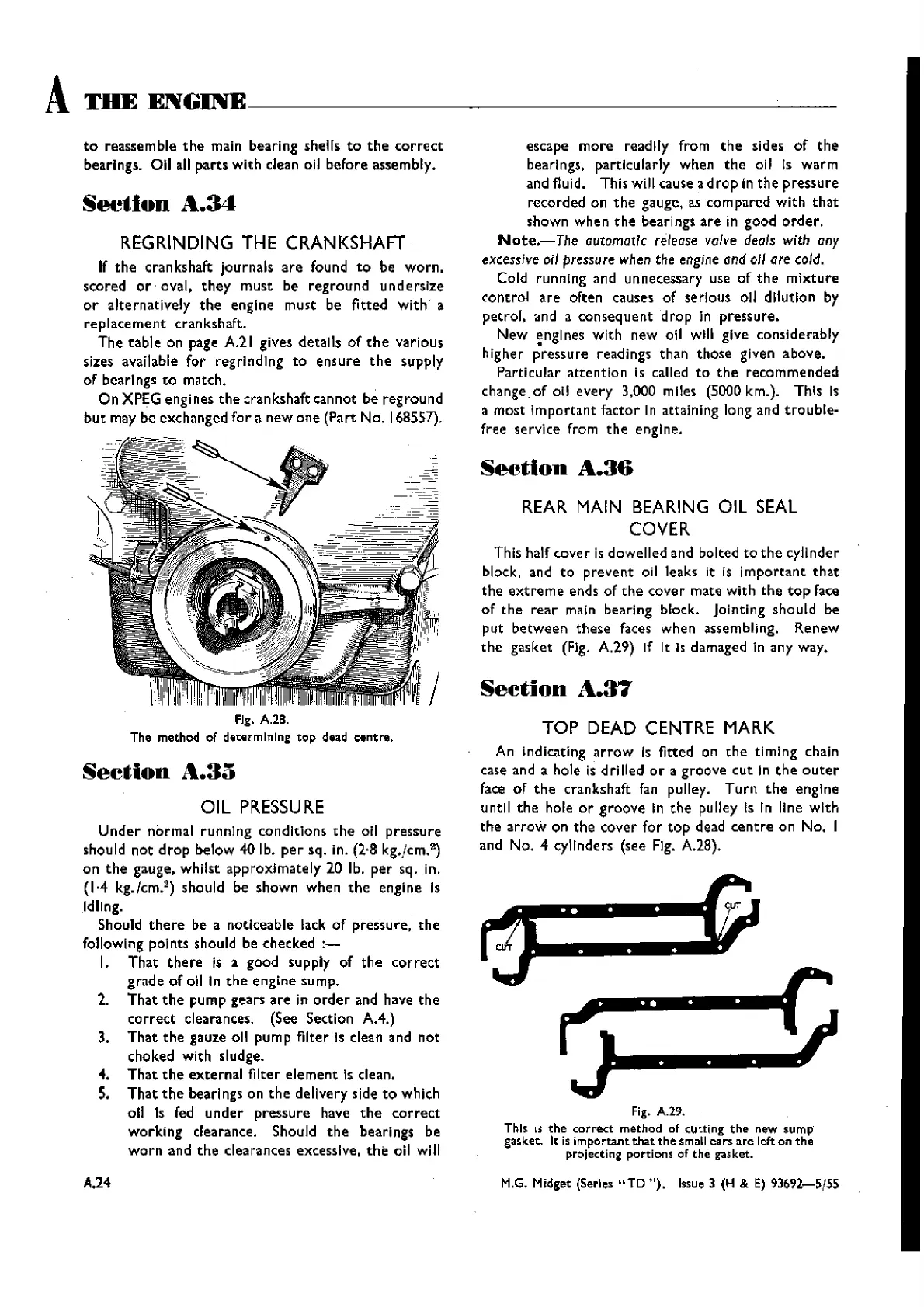
FIg. A.2B.
The method of
determining
top
dead
centre.
Section
A.35
OIL
PRESSURE
Under
normal
running
conditions
the
011
pressure
should
not
drop
below 40 lb.
per
sq. in. (2,8 kg./ern.
ll
)
on
the
gauge, whilst
approximately
20 lb.
per
sq. in.
(1·4 kg.
[cs».
2)
shouId be
shown
whe n
the
engi ne Is
Idling.
Should
there
be a noticeable lack
of
pressure.
the
following points should be checked
:-
I.
That
there
Is a good supply of
the
correct
grade
of
oil In
the
engine
sump.
2.
That
the
pump
gears
are
in
order
and have
the
correct
clearances. (See Section AA.)
3.
That
the
gauze all
pump
filter Is clean and
not
choked with sludge.
4.
That
the
external
filter
element
Is clean.
S.
That
the
bearings on
the
delivery side
to
which
oil Is fed
under
pressure
have
the
correct
working
clearance. Should
the
bearings be
worn
and
the
clearances excessive,
the
all will
A.24
escape
more
readily from
the
sides
of
the
bearings, particularly when
the
oil Is
warm
and fluid. This will cause
ad
rop
In
the
pressure
recorded
on
the
gauge, as
compared
with
that
shown
when
the
bearings
are
in
good
order.
Note.-The
automatic
release
valve deals with any
excessive oil pressure when the engine and
01/
are cold.
Cold running and unnecessary use
of
the
mixture
control
are
often causes
of
serious all dilution by
petrol,
and a
consequentd
rap
In
pressure.
New
;nglnes
with
new all wIll give considerably
higher
pressure
readings
than
those
given above.
Particular
attention
is called
to
the
recommended
change _
of
011
eve ry 3,000 miles (5000 km.). This Is
a
most
Important
factor
In attaining long and
trouble-
free service from
the
engi ne,
Section
A.36
REAR MAIN BEARING OIL SEAL
COVER
This half
cover
is dowelled and bolted
to
the
cylinder
block, and
to
prevent
oil leaks it is
important
that
the
extreme
ends
of
the
cover
mate
with
the
top
face
of
the
rear
main bearing block. Jointing
should
be
put
between
these
faces when assembling.
Renew
the
gasket
(Fig. A.29) if It is damaged In any way.
Section
1\.37
TOP DEAD CENTRE MARK
An indicating
arrow
Is fitted on
the
timing
chain
case and
a hole is
drilled
or
a
groove
cut
In
the
outer
face
of
the
crankshaft fan pulley,
Turn
the
engine
until
the
hole
or
groove
in
the
pulley is in line
with
the
arrow
on
the
cover
for
top
dead
centre
on
No.
I
and
No.4
cylinders (see Fig. A.28).
..
.. . .
..
. .
..
Fig. A.29.
This
I.
the
correct
method
of cutting
the
new
sump
gasket. It is
important
that
the
small
ears
are
left on
the
projecting portions of the gasketo
M.G. Midget (Series
"TD
").
Issue 3 (H & E) 936'J2-5/55
Wishvilles Classic
Automobile Library

 Loading...


