NELECTRICAL EQUIPMENT
Seetion
N.12
THE CONTROL BOX
Regulator
adjustment
The
regulator
is carefully
set
before leaving
the
Works
to
suit
the
normal
requirements
of
the
standard
equipment, and in general It should
not
be necessary
to
alter
it. If. however.
the
battery
does
not
keep in
a charged condition,
or
if
the
dynamo
output
does
not
fall
when
the
battery
is fully charged. it may be
advisable
to
check
the
setting
and if necessary
to
re-
adjust it.
SPARE
FUSES
FUSES
IN Cl
RCU
ITS
OF ACCESSOR IES
Fig.
N.16.
The control box on early
models,
showing
the
location
of the
fuses.
Oil later
models
a separate
ruse
box i$
fitted (see fig. N.21).
It is
important.
before altering
the
regulator
setting.
when
the
battery
is in a low state of charge,
to
check
that
its condition Is not
due
to
a
battery
defect
or
to
the
dynamo belt slipping.
How
to check andadjust electrical
setting
The
regulator
setting
can be checked
without
re-
moving
the
cover
on
the
control
box.
Withdraw
the
cables from
the
terminals marked
"A"
and
"A.I
" at
the
control
box
and Join
them
together.
Connect
the
negative lead of a moving
coil
voltmeter
(0-20
volts full scale reading)
to
the
" D .. terminal on
the
dynamo and connect
the
other
lead from
the
meter
to
a convenient chassis
earth.
Slowly increase
the
speed of
the
engine until
the
voltmeter
needle ..
flicks"
and
then
steadies;
thls
should
occur
at a
voltmeter
reading
between
the
limits
given In
the
next
column for
the
appropriate
tern-
perature
of
the
regulator.
N.12
Setting at 10
0
C. (50
0
F.) 16·1-16·7 volts
.. 20° C. (68° F.)
r5·8--- r6·4 "
.. .. 30°
C. (86° F.) 15·6-16·2 ..
..
,,40
0
C. (104
0
F.) 15·3-15·9 ..
If
the
voltage at which
the
reading becomes steady
occurs
outside
these
llrnlts,
the
regulator must be
adjusted.
Shut off
the
engine. remove
the
control
box cover,
release
the
lockn ut
"A"
(Fig. N.17) holdIng
the
adjusting
screw"
B."
The
screw
turns
in a clock-
wise direction
to
raise
the
Setting
or
in an
antl-
clockwise direction
to
lower
the
setting.
Turn
the
adjusting
screw
a fraction of a
turn
in
the
required
direction and
then
tighten
the
locknut.
When
the
dynamo is run at a high speed on open
circuit it builds up a high voltage.
When
adjustIng
the
regulator
do
not
run
the
engine up
to
more
than
half-throttle
or
a false
voltmeter
reading will be
obtained.
Mechanical
setting
The
mechanical
settl
ng of
the
regu I
ator
is accurate Iy
adjusted before
leaving
the
Works.
and provided
that
the
armature
carrying
the
moving
contact
Is
not
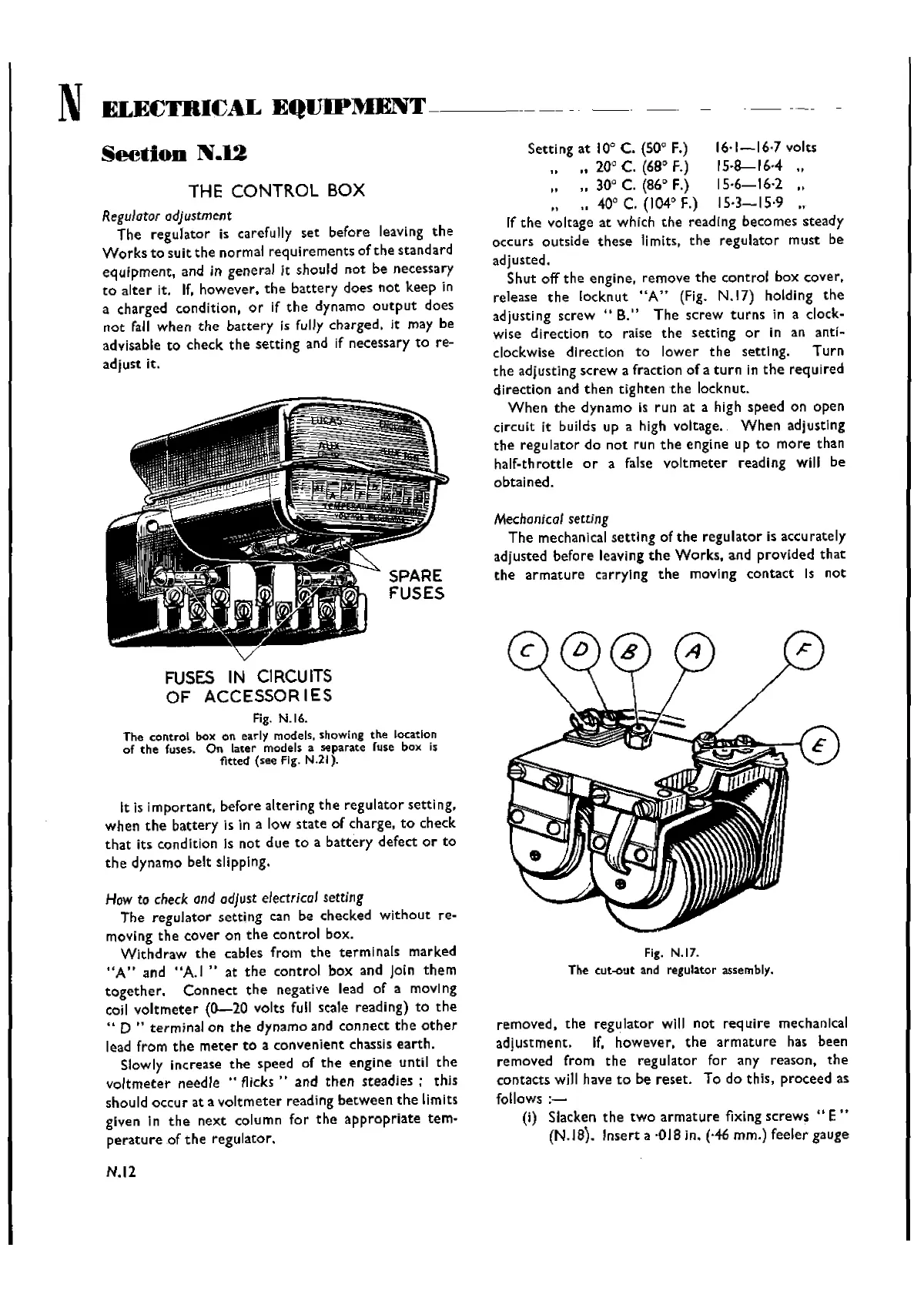
Fig.
N.ll.
The cut-out
and
regulator
assembly.
removed.
the
regulator
will
not
require
mechanical
adjustment. If. however.
the
armature
has been
removed from
the
regulator for any reason.
the
contacts will have
to
be
reset.
To do thls, proceed as
follows
:-
(i) Slacken
the
two
armature
fixing screws
"E"
(N.18). Insert a ·018 in. (,46 rnm.) feeler gauge
Wishvilles Classic
Automobile Library

 Loading...


