J
THE
STEERING GEAR
-------
----
--
.-
----~---------
Make
sure
that
the
oil
groove
is fitted
to
the
top
when
reaming.
Check
the
felt
washer
and
the
rubber
bellows and
renew
If necessary.
Examine
the
steering
rod balls and caps
for
wear
and
renew
as necessary
or
readjust
as
detailed
later.
Replacement
Is a reversal of
the
above
process.
Note.-When
rep/acing the
pinion
shaft see that the
thrust
washers
have their chamfered sides
towards
the
pInion.
End
float
should
be ·002 In.(OS mm.) to ·005 in.
(,13 mm.) and is
set
by
the shims.
The
oilway in
the
cap
should
be at
the
top
and
the
damper
pad must be
adjusted
as
detailed
under
J.7.
With
the
rack
in
the
central
position
engage
the
pinion
with
the
arrow
uppermost.
Refit
the
coupling
with
a coupling
bolt
In line
with
the
arrow
on
the
shaft. This will ensure
that
the
steering
wheel
spokes
are
in
the
correct
position
In
the
car.
011 all
parts
before
reassembling and refill
the
box
with
-i-
pint
(,4
litre)
of
lubricant
as specified on
page
P.2 (Ref.
B).
Soodon
J.6
ADJUSTMENT OF THE
INNER
STEERING
BALL
JOINT
Fit
the
lock
plate
and shims and
screw
home
the
ball
seat
housing
into
the
rack
bar.
Insert
the
ball
seat.
Screw
the
ball cap
home
against its
shoulder
after
In
sertl
ng
the
bail-a nded tie-
rod.
The ball
sho
uld have
no play,
but
must
be a
free
roll i
ng
f t, Ad justm
ent
can
be
altered
by varying
the
shims, which
are
supplied In
·003 In. ('08
mm.)
and ·005 in.
(,13
rnm.) slzes,
Section
J.':
ADJUSTMENT OF
THE
RACK
DAMPER
This is
provided
to
ensure
the
required
amount
of
damping
In
the
steering
tie-rods,
and
to
maintain
the
minimum
of
backlash in
the
gear
teeth.
This
should
_be
adjusted
in
the
followlng
manner
:-
Check
the
damper
spring, which
should
have a free
length
of
approximately
1·024 in. (26'01 mrn.), and
should
give a load
of
80 lb. (36,3 kg.)
when
compressed
to
·75 in. (19,05
mm.).
When
the
steering
gearbox
is
completely
assembled,
fit
the
plunger,
spring
and cap,
but
omit
the
shims.
Screw
down
the
cap until
the
plunger
bottoms.
While
screwing
down
the
plunger
rotate
the
pinion
shaft.
When
it is felt
to
just lock
the
rack bar In
the
houslng t he pl
unger
has
bottomed.
With
fee
ler
gauges
take
a
measurement
of
the
gap
left
and add
to
this
measurement
·051 in. (1·30 rnrn.].
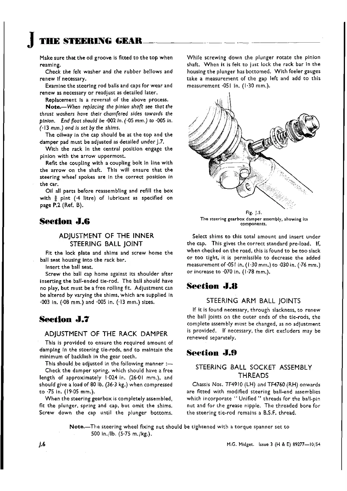
Fig. ).5.
The steering gearbox damper assembly, showing its
components.
Select
shims
to
this
total
amou
nt
and
insert
under
the
cap. This gives
the
correct
standard
pre-load.
If,
when
checked
on
the
road, th is is fou nd
to
be
too
slack
or
too
tight,
it is
permissible
to
decrease
the
added
measurement
of
·05 I in. (1,30
rnrn.]
to
·030 in. (·76 mm.)
or
increase
to ·070 in. (1'78 rnrn.},
Section
J.B
STEERING ARM BALL JOINTS
If it is found necessary,
through
slackness,
to
renew
the
ball joints on
the
outer
ends
of
the
tie-rods,
the
complete
assembly
must
be changed, as no
adjustment
is
provided.
If necessary,
the
dirt
excluders
may be
renewed
separately.
Set~tion
.1.9
STEERING
BALL
SOCKET ASSEMBLY
THREADS
Chassis Nos.
TF49
10(LH) and TF4760
(R.H)
onwards
are
fitted
with
modified
steering
ball-end assemblies
which
incorporate"
Unified"
threads
for
the
ball-pin
nut
and
for
the
grease
nipple.
The
threaded
bore
for
the
steering
tie-rod
remains a B.S.F.
thread,
).6
Note.-The
steering
wheel
fixing
nut
should
be
tightened
with
a
torque
spanner
set
to
500
in.jlb.
(5,75 rn.rkg.).
M.G. Midget. issue 3 (H & E)
89277-10/54
Wishvilles Classic
Automobile Library

 Loading...


