-~-----------TIIE
FRONT SUSPENSION K
retalners
are
assembled In
the
right
order.
(See
Fig. K
.....
)
Lubricate
these
parts
and
the
fulcrum pins
during
assembly
and
again
afterwards
with
the
grease
gun.
using
the
recommended
lubricant
as detailed on page
P.l.
Do
not
tighten
up
the
top
or
the
bottom
slotted
nuts
solid.
but
leave
them
half a
turn
slack.
Connect
up
the
hydnulic
brake
hoses. See
correct
method
as expjaJned on page M.1l.
Screw
the
steering
tie-rods
Into
the
outer
steering
ball
[olnts,
Screw
the
rods
right
in and
then
slack off
five
complete
turns.
This will give a rough
wheel
alignment
and
render
subsequent
accurate
alignment
easier.
Bleed and adjust
the
front
brakes as detailed In
Sections
M.2 and M.3.
EO U 101
STANT
Fie.
K.S.
The
correct
method of clamping the rubber bushes of
the
lower suspension arm.
Fit
the
front
wheels.
Bounce
the
front
end
of
the
car up and
down
a few
times.
This allows
the
suspension fulcrums
to
settle
down.
Now
tighten
the
spring
pan bolts and
then
tighten
and
cotter
up
the
outer
fulcrum bolts.
Check
and
adjust
the
front
wheel alignment as
detailed in Section K.1.
Seedon
K.ll
REASSEMBLY
OF
SWIVEL
PINS
The
swivel pin assembly may bereassembled
without
difficulty by carrying
out
the
removal
instructions
in
the
reverse
order,
provided
the
following points
are
given special
attention
:-
I.
The
swivel pin
and
Jinks fitted
to
the
left-hand
side
of
the
ca.r have left-hand
threads
at each
end
and
those
fitted
to
the
right-hand side have
right-hand
threads.
2.
The
swivel pin links
screw
onto
threads
on
each
end
of
the
swivel pIn and
the
threads
are
waisted
at
their
centre
to
avoid fouling
the
pivot
bolts passing
through
the
links. Before
the
pivot
bolt
is replaced
the
link
must
be
correctly
positioned on
the
thread.
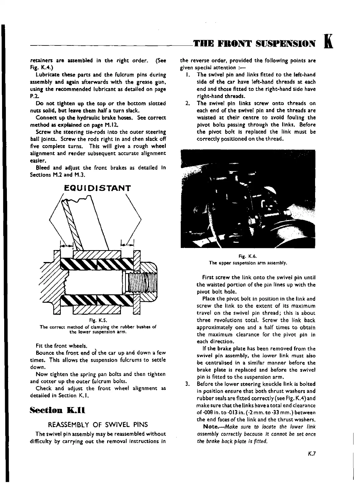
Fig. K.6.
The
upper suspension arm assembly.
First
screw
the
link
onto
the
swivel pin until
the
waisted
portion
of
the
pin lines up With
the
pivot
bolt
hole.
Place
the
pivot
bolt
in position in
the
link and
screw
the
link
to
the
extent
of its maximum
travel on
the
swivel pin
thread;
this
is
about
three
revolutions
total.
Screw
the
link back
approximately
one
and a half
times
to
obtain
the
maximum clearance for
the
pivot pin in
each
direction.
If
the
brake plate has been removed from
the
swivel pin assembly.
the
lower
link
must
also
be centralised
In a similar
manner
before
the
brake
plate is replaced and before
the
swivel
pin Is
fitted
to
the
suspension
arm.
3. Before
the
lower
steering
knuckle link is bolted
in positlon ens ure
that
both
th
rust
washers and
ru
bber
seals
are
fitted
correctly
(see
Fig.
KA)
an
d
make
sure
that
the
links have a
total
end clearance
of ·008 in.
to-013
in.
(·2mm.to
·33 mm.)
between
the
end faces of
the
link and
the
th
rust
washers.
Note.-Moke
sure to locate the lower link
assembly correctly because
It
cannot be set once
the brake back plate is fitted.
K.7
Wishvilles Classic
Automobile Library

 Loading...


