M
THE
BRAKING
SYSTEM---------------
MAINTENANCE
Periodically examine
the
quantity of
brake
fluid in
the
master
cylinder. It should
never
be less
than
half
full
or
closer
than
tin.
(13 mm.) from
the
bottom
of
the
filler neck.
The
necessity for freq
uent
topping
up is an Indication of over-filllng
or
a leak in
the
system. which should at
once
be
traced
and rectified.
Adjust
the
brake-shoes
to
compensate
for
wear
of
the
linings.
The
need for
this
is shown by
the
pedal
going
down
almost
to
the
floorboards before solid
resistance is felt. For brake-shoe
adjustments
see
Section
M.2.
Adjustment
of
the
brake-shoes In
the
manner
Indicated also adjusts
the
hand brake automatically
and no
separate
adjustment
is
required
or
permitted.
THE
MASTER
CYLINDER
The
master
cylinder is
mounted
on
the
driver's
side of
the
car
underneath
the
gearbox
cover.
Within
the
cylinder is a piston, backed by a
rubber
cup. normally held in
the"
off"
position by a piston
retu
rn spri ng. lrnmed late Iy in
front
of
the
cup.
when
it is In
the
..
off"
position, is a compensattng orifice
connecting
the
cylinder with
the
fluid supply. This
port
allows
free
compensation for any expansion
or
contraction
of
the
fluid,
thus
ensuring
that
the
system
is constantly
filled;
it also serves as a release
for
additional fluid drawn
into
the
system during brake
applications. Pressu re is applied
to
the
piston by
means of
the
push-rod attached
to
the
brake
pedal.
The push-rod is adjustable and should have a slight
clearance
when
the
system is at
rest
to allow
the
piston
to
return
fully against its
stop.
Without
thls
clearance ehe main cup will
cover
the
by-pass
port,
causing pressure
to
build up within
the
system. and
produce
binding of
the
brakes on all wheels.
The
reduced
skirt
of
the
piston forms an annular space
M.4
which is filled with fluid from
the
supply
tank
via
the
feed hole. Leakage of fluid from
the
open
end of
the
cylinder is
prevented
by
the
secondary cup fitted
to
the
flange end of
the
piston. On releasing
the
brake
pedal, afte r ap piicatio n,
the
pisto n is reeurned quickly
to its
stop
by
the
return
spring,
thus
creating a vacuum
in
the
cylinder;
this vacuum causes
the
main cup
to
collapse and pass fluid
through
the
small holes In
the
piston head from
the
annular space formed by
the
piston ski rt. This additional fluid finds Its way back.
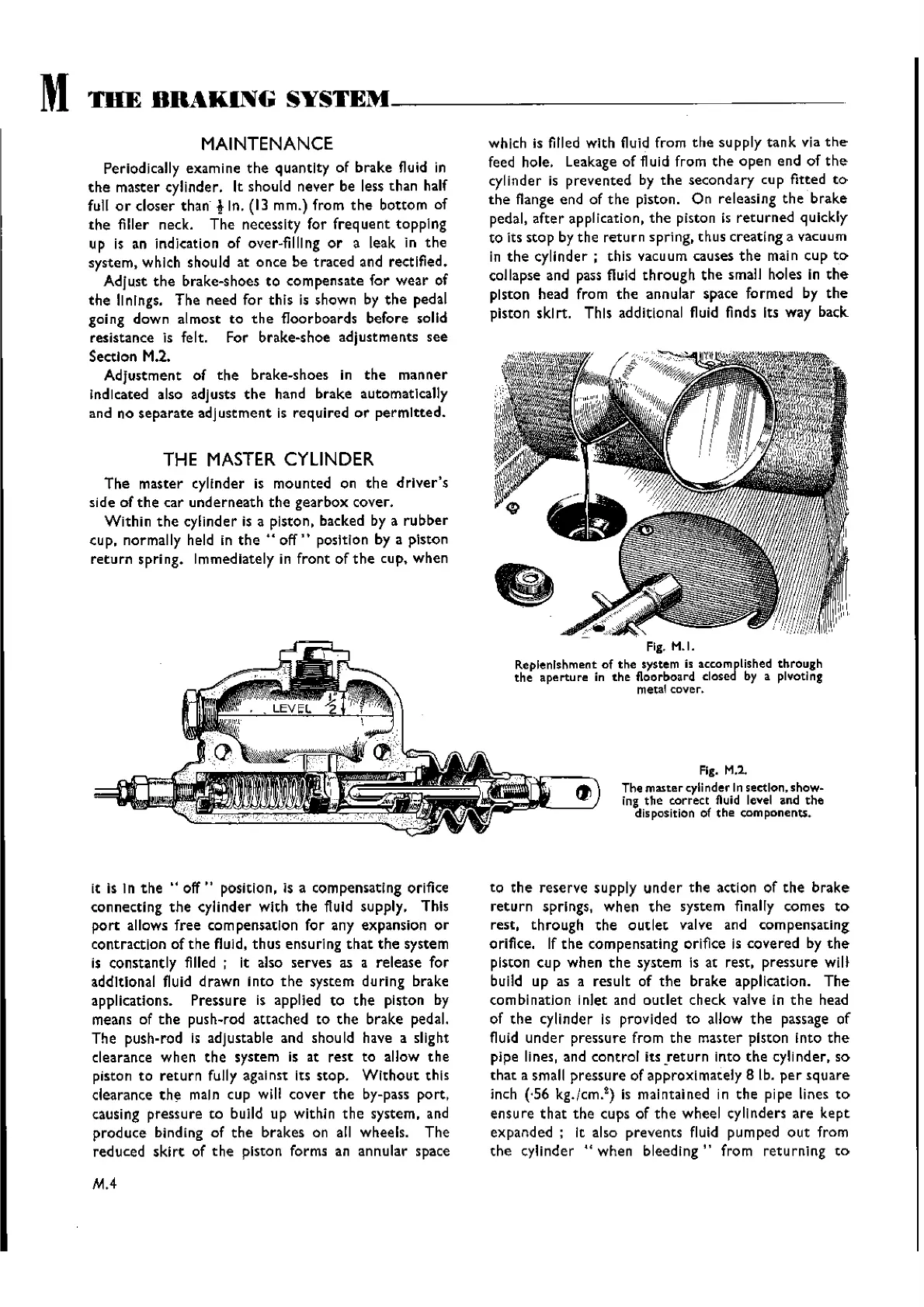
Fig.
H.I.
Replenishment of
the
system is accomplished
through
the
ape rtu re in
the
floorboard closed by a plvotl ng
metal cover.
Fig.
M.l.
The
master
cylinder In section. show-
ing
the
correct fluid level and the
disposition of
the
components.
to
the
reserve
supply
under
the
action of
the
brake
return
springs.
when
the
system finally comes
to
rest,
through
the
outlet
valve and
compensating
orifice. If
the
compensating orifice is
covered
by
the
piston
cup
when
the
system Is at rest,
pressure
wil.
build up as a
result
of
the
brake application.
The
combination inlet and
outlet
check valve in
the
head
of
the
cylinder Is provided
to
allow
the
passage of
fluid
under
pressure from
the
master
piston
into
the
pipe lines, and
control
its
!eturn
into
the
cylinder, so
that
a small
pressure
of
apprcxlmately
8 lb.
per
square
inch (·56 kg./cm.
2
)
is maintained in
the
pipe lines
to
ensure
that
the
cups of
the
wheel cylinders
are
kept
expanded;
It also
prevents
fluid pumped
out
from
the
cylinder
"when
bleeding ,. from
returning
to
Wishvilles Classic
Automobile Library

 Loading...


