A
TOE
ENGINE---~----------~
Section
A.IO
REMOVAL
AND
REPLACEMENT
OF
PISTONS
AND CONNECTING
RODS
Follow
the
dismantling
procedure
as
set
out
in
Section
A.7 and
withdraw
the
piston and
connecting
rod
assembly carefully past
the
crankshaft On
the
left-
hand side
of
the
engine,
rotating
the
crankshaft as
necessary
to
give
the
required
clearance.
Note.--:-It
/s essential that pistons be fitted in the same
bores as they were be(ore removaf. The gudgeon pin
pinch-bolt must be on the right-hand side o( the engine.
The
same connecting
rod
andcap,completewith bearings,
must befitted to the
jOu
rnaI (rom wh
ich
they were removed.
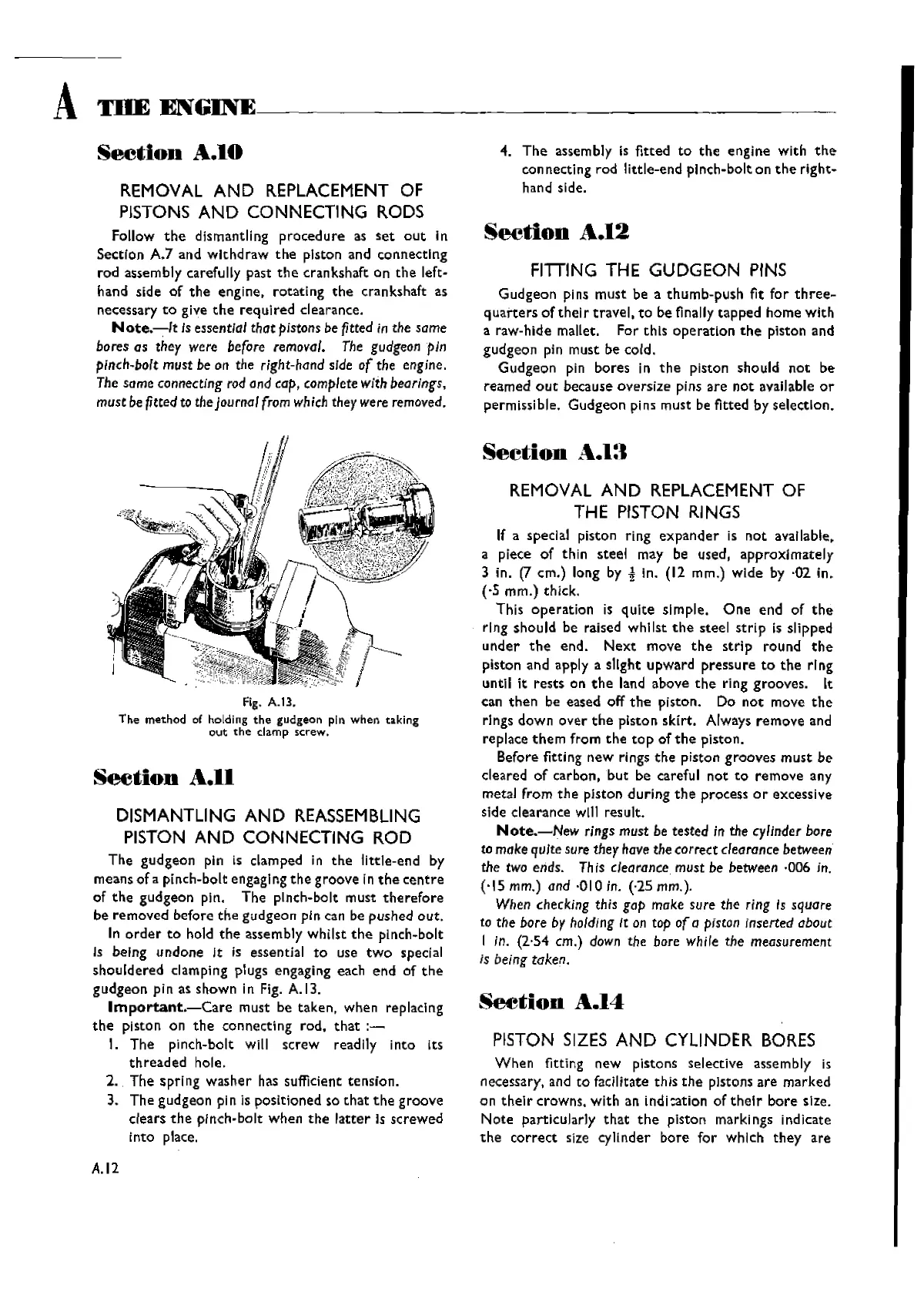
Fig.
A.B.
Tile method of
holding
tile gudgeon pin
when
taking
out
the
damp
screw.
See:tion
A.II
DISMANTLING
AND
REASSEMBLING
PISTON
AND CONNECTING ROD
The
gudgeon
pin is clamped in
the
little-end
by
means
of
a pinch-bolt engagi ng
the
groove
in
the
centre
of
the
gudgeon
pin.
The
pinch-bolt must
therefore
be
removed
before
the
gudgeon
pin can be
pushed
out.
In
order
to
hold
the
assembly
whilst
the
pinch-bolt
Is being
undone
It Is essential
to
use
two
special
shouldered
clamping plugs engaging each
end
of
the
gudgeon
pin as
shown
in Fig. A.13.
Irnportant.-Care
must be
taken,
when replaclng
the
piston on
the
connecting
rod,
that
:-
I.
The
pinch-bolt will
screw
readily
into
Its
threaded
hole.
2.
The
spring
washer
has sufficient
tension.
3.
The
gudgeon
pin is
positioned
so
that
the
groove
dears
the
pinch-bolt
when
the
latter
Is
screwed
into
place.
A.12
4.
The
assembly is
fitted
to
the
engine
with
the
con necti ng
rod
I
ittle-end
pinch-bolt on
the
right-
hand side.
Seetion
A.12
FITTING
THE GUDGEON
PINS
Gudgeon
pins
must
be a
thumb-push
fit
for
three-
quarters
oftheir
travel,
to
be finally
tapped
home
with
a raw-hide mallet. For
this
operation
the
piston and
gudgeon
pin
must
be cold.
Gudgeon
pin
bores
in
the
piston should
not
be
reamed
out
because
oversize
pins
are
not
available
or
permissible.
Gudgeon
pins must be fitted by
selection.
Section
..
:\..1:1
REMOVAL
AND
REPLACEMENT
OF
THE
PISTON
RINGS
If a speclal piston ring
expander
is
not
available.
a piece
of
thin
steel
may be used,
approximately
3 in.
[T
crn.) long by i In. (12 mm.)
wide
by ·02
in.
(,5
mm.)
thick.
This
operation
is
quite
simple.
One
end
of
the
ring
should
be raised
whilst
the
steel
strip
is slipped
under
the
end.
Next
move
the
strip
round
the
piston and apply a slight
upward
pressure
to
the
ring
until it
rests
on
the
land above
the
ring
grooves.
It
can
then
be eased off
the
piston. Do
not
move
the
rings
down
over
the
piston
skirt.
Always
remove
and
replace
them
from
the
top
of
the
piston.
Before fitting
new
rings
the
piston
grooves
must
be
cleared
of
carbon,
but
be careful
not
to
remove
any
metal
from
the
pIston
during
the
process
or
excessive
side clearance
will result.
Note.-New
rings must be tested in the cylinder
bore
to make quite
sure
they havethe correct clearancebetween
the two ends. This clearance must be between ·006 in.
('15
mm.) and ·010 in. (·25 mm.).
When checking this gap make sure the ring Is
square
to the bore by holding
It
on top
of
a
piscon
inserted about
I in. (2'54 em.)
down
the bore
While
the measurement
is being taken.
Seetion
A.14
PISTON
SIZES
AND
CYLINDER
BORES
When
fitting
new
pistons selective assembly is
necessary, and
to
facilitate this
the
pIstons
are
marked
on
their
crowns.
with
an
indi:ation
of
their
bore
size.
N
ate
particularly
that
the
piston
marki ngs ind
kate
the
correct
size
cylinder
bore
for
which
they
are
Wishvilles Classic
Automobile Library

 Loading...


