--------------THE
(;OOLING
SYSTEM
D
Take
out
the
set
bolts and
remove
the
pump unit
by breaking
the
[olnt
between
the
impeller housing
flange and
the
cylinder block. moving
the
inner
control
link
bracket
outwards
to
clear.
Dismantle
the
pump by removing
the
impeller from
the
shaft. tapping
out
the
taper
pin attaching it
to
the
shaft and taking care
to
see
that
it is knocked
out
in
the
right direction.
Withdraw
the
pressure
spring
and washer. which gives access to
the
carbon seal and
gland
washer
assembly.
Care
should be taken
not
to
damage
the
carbon ring. which is relatively
brittle,
the
working face of
the
rubber
seal, and
not
to
lose
of
the
spindle on a plec:e of
wood
until
the
outer
bearing can be
withdrawn.
This will release
the
distance-plece
between
the
bearings, which can be
withdrawn.
giving access
to
the
Inner race.
Remove
the
Inner
drclip
by
contracting
the
ring
and inserting a
screwdriver
behind it
to
ease It
out
of
its groove.
After
removal
of
the
clrdip
the
retaining
bearing and
the
impeller spindle can be
withdrawn.
If
the
felt
011
sealing rings
are
badly
worn
or
the
bearings unduly slack,
they
should be
renewed.
Care-
fully examine
the
carbon
sealing ring
for
cracks
or
undue
wear
and
renew
if necessary. The face of
the
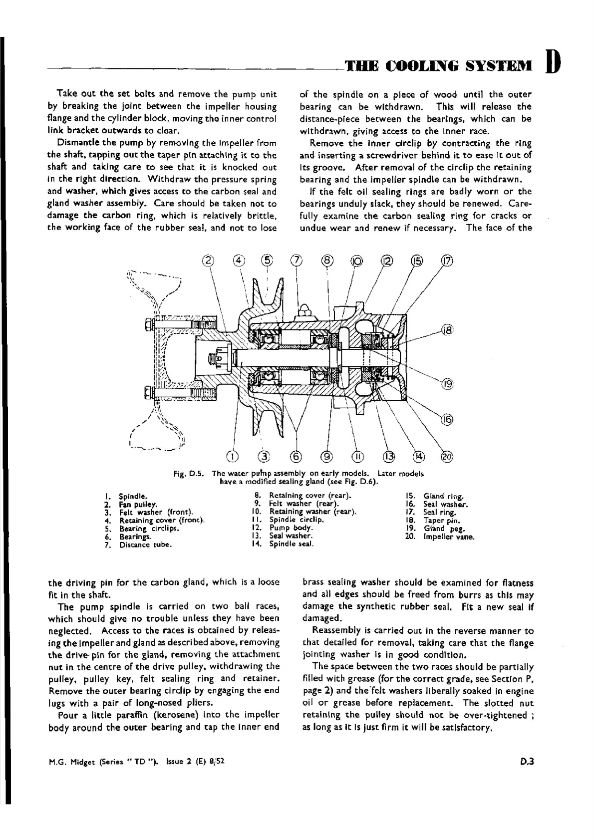
15. Gland ring.
16. Seal washer.
17. Seal
ring.
18. Taper pin.
19.
Gland peg.
20. Impeller vane.
fig. D.S.
I. Spindle .
2.
Fan
pulley.
3.
felt
~her
(front).
4. Retaining
cover
(front).
5.
Bearing clreli ps.
6.
Bearings.
7. Distance tube.
\ \ \ \
®
~
'@
The
water
pump
usembly
on
early
models.
later
models
have
a modified sealing gland (see Fig. D.6).
8. Retaining
c:ov
er (r
ear).
9. Felt washer (rear).
10. Retaining wasner
(rear)
.
II.
Spindle c:irdip.
12. Pump
body.
13. Seal
washer.
14. Spindle seal.
17
o
the
driving pin for
the
carbon gland, which is a loose
fit
in
the
shaft.
The
pump spindle is carried on
two
ball races,
which should give no
trouble
unless
they
have been
neglected. Access
to
the
races is
obtained
by releas-
ing
the
impe ller and gland as descrlbed above, removing
the
drive· pin
for
the
gland. removing
the
attachment
nut
in
the
centre
of
the
drive
pulley.
withdrawing
the
pulley, pulley key. felt sealing ring and
retainer.
Remove
the
outer
bearing c1rcllp by engaging
the
end
lugs
with
a pair of long-nosed pliers.
Pour
a little paraffin
(kerosene)
Into
the
impeller
body around
the
outer
bearing and
tap
the
inner
end
M.G. Midget (Series ,. TD
"],
lssue 2 (E) SiS
2
brass sealing washer should be exam ined for flatness
and all edges should be freed from
burrs
as
this
may
damage
the
synthetic
rubber
seal.
fit
a new seal If
damaged.
Reassembly is carried
out
in
the
reverse
manner
to
that
detailed for removal, taking care
that
the
flange
jointing
washer
Is in
good
condition.
The
space
between
the
two
races should be partially
filled with grease (for
the
correct
grade. see Section P.
page 2) and
thefelt
washers liberally soaked in
engine
oil
or
grease before replacement.
The
slotted
nut
retaining
the
pulley should
not
be
ever-tightened
;
as long as
it
Is Just firm it will be satisfactory.
D,3
Wishvilles Classic
Automobile Library

 Loading...


