-
184
-
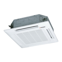
(c) Ceiling cassette-2 way type (FDTW)
(i) Selection of installation location
1) This unit is a ceiling surface direct return air and direct supply air type.
Install the unit a place the allows air to reach every part of the room, in accordance with the shape and heigh of the room.
• Installation space
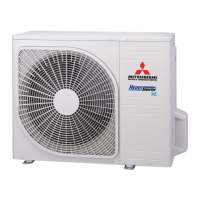
2) This unit permits connecting a branch duct (
φ200 mm) according to the method shown in the figure below so that air
disribution may be improved to the shape of the room. (For the connecting port of the duct, refer to the exterior dimension
on page 40 ~ 42.)
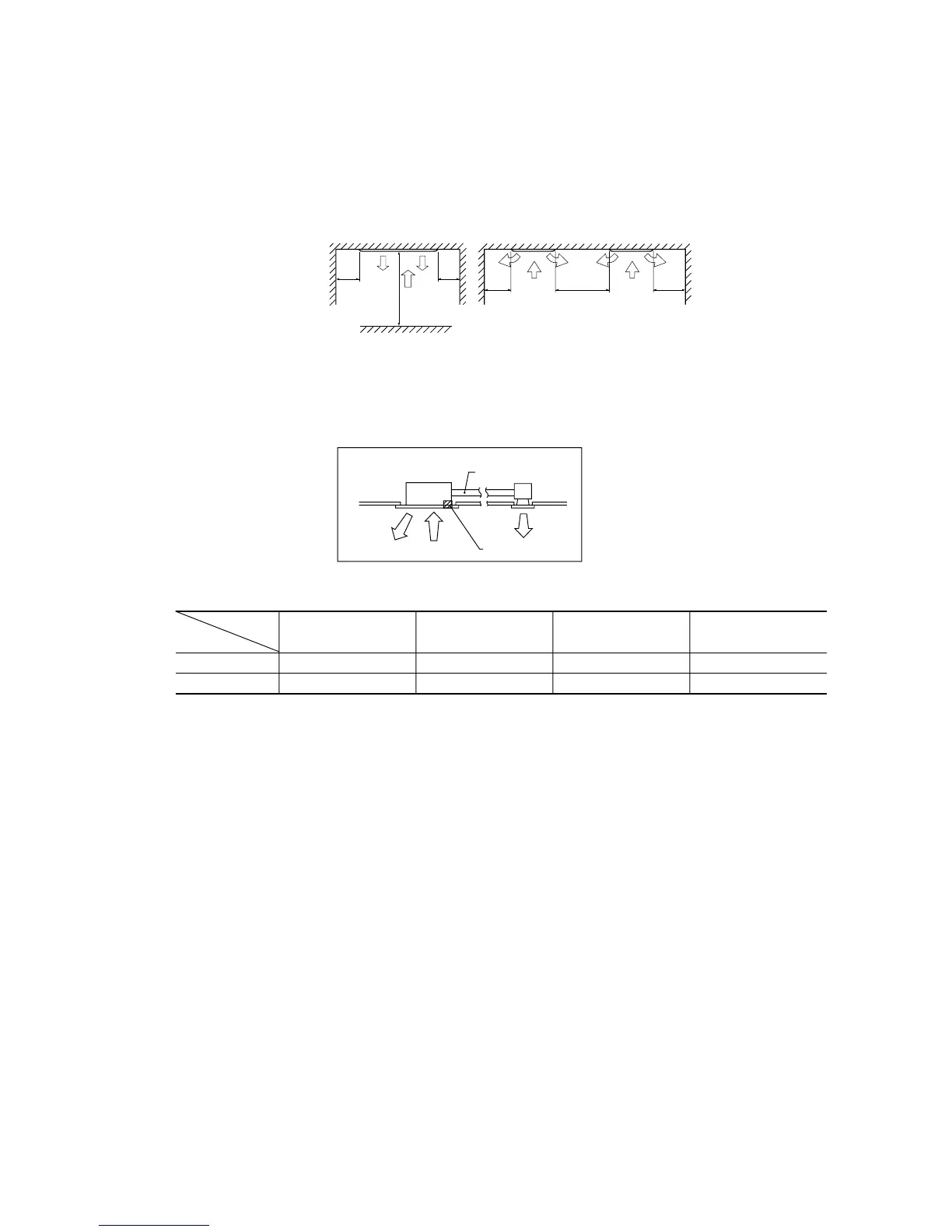
3) Cold air throw
Note (1) The cold air throw is the same in 2 directions.
Conditions:
1.Unit height: 3.0 m above the floor
2.Fan speed: Hi
3.Location: Freee space without obstacle
4.The throw is as the per the table above.
5.Air velocity at the throw: 0.3(m/s)
4) Places where cool or heated air circulates freely. When the installation height exceeds 3.0m, warmed air stays close to the
ceiling. In such cases, suggest your client users to install air circulators.
5) Places where perfect drainage can be prepared and sufficient drainage gradient is available.
6) Places free from air disturbances to the return air port and supply hole of the indoor unit, places where the fire alarm may
not malfunction to short circuit.
7) If the humidity above the ceiling exceeds 80% or the condensation temperature above the ceiling exceeds 28ºC, affix
polyurethane foam (with a thickness to 10 or greater) above the insulation in the ceiling panels.
Carry out tests of the main unit under the above conditions and confirm that there is no failure. However, if the
environment where the unit is installed exceeds the above conditions and the unit is operated in high humidity
conditions, there is danger of condensate dripping down. If there is a possibility that the unit will be used under
such conditions, dress 10 to 20 mm of insulation material to the main unit, piping and drain pipes.
Item
Models
FDTW28, 45, 56 FDTW71, 90 FDTW112 FDTW140
Standerd
UHi
4.0
4.5
4.5
5.0
4.7
5.2
5.0
5.5
Unit : m
1,500
or
more
3,000 or more
(1)
1,500
or
more
100
or
more
100
or
more
1,000 or more
Unit : mm
φ200 mm
Air interruption
()
Note (1) This shows the installation interval dimensions between units.
 Loading...