-
252
-
Method of connecting power cables
q Method of leading out cables
● As shown on the drawing in Section 4-2, cables can be laid through the front, right, left or bottom casing.
● In wiring on the installation site, cut off a half-blank covering a penetration of the casing with nippers.
● In the case of an installation using a collective drain system, use a port other than the bottom one to take out cables and
pipes.
If the bottom port is used, seal it thoroughly so that drain water may not spill out.
w Notabilia in connecting power cables
● Connect the ground wire before you connect the power cable. When you connect a grounding wire to a terminal block,
use a grounding wire longer than the power cable so that it may not be subject to tension.
● Do not turn on power until installation work is completed. Turn off power to the unit before you service the unit.
● Always connect power cables to the power terminal block.
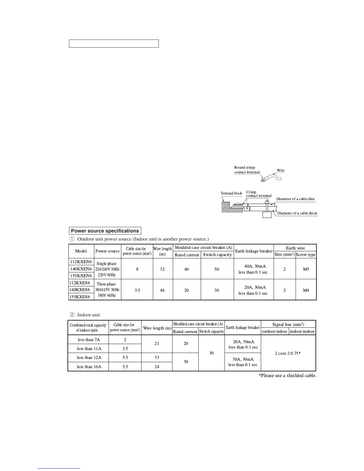
● To connect a cable to the power terminal block, use a round crimp contact terminal.
If two cables are to be connected to one terminal, arrange cables in such a manner that you put their crimp contact
terminals together back to back. Further, put the thinner cable above the thicker one in arranging cables for such
connection.
● Use specified wires in wiring, and fasten them securely in such a
manner that the terminal blocks are not subject to external force.
● In fastening a screw of a terminal block, use a correct-size driver.
Fastening a screw of a terminal block with excessive force can break
the screw.
● When electrical installation work is completed, make sure that all
electrical components within the electrical component box are free
of loose connector coupling or terminal connection.
Power source specifications
q Outdoor unit power source (Indoor unit is another power source.)
w Indoor unit power source (Outdoor unit is another power source.) & signal line
Please note
a) The method of laying cables has been determined pursuant to the Japanese indoor wiring regulations (JEAC8001).
(Please adapt it to the regulations in effect in each country)
b) Wire length in the table above is the value for when the indoor unit is connect to the power cable in series also the wire
size and minimum length when the power drop is less than 2% are shown. If the current exceeds the value in the table
above, change the wire size according to the indoor wiring regulations. (Please adapt it to the regulations in effect in each
country)
c) For details, please refer to the installation manual supplied with the indoor unit.
40A, 30mA
less than 0.1 sec
8
112KXEN6
140KXEN6
155KXEN6
112KXES6
140KXES6
155KXES6
Single-phase
220/240V 50Hz
220V 60Hz
Three-phase
380/415V 50Hz
380V 60Hz
32 40 50 2 M5
20A, 30mA
less than 0.1 sec
3.5 46 20 30 2 M4
Model
Power source
Cable size for
power source (mm
2
)
Wire length
(m)
Rated current
Switch capacity
Size (mm
2
)
Screw type
Moulded-case circuit breaker (A)
Earth wire
Earth leakage breaker
!
"# $%
& % $%
#
#
'$ !
(
'$ ) (
*
+
, $
 Loading...