-
237
-
(c) Recessed fitting
1) The Electrical box and remote controller (shield
wire must be use in case of extension) are first
embedded.
(2) Installation of remote controller
(Option parts)
(a) Selection of installation location
Avoid the following locations
1) Direct sunlight.
2) Close to heating device.
3) Highly humid or water splashing area.
4) Uneven surface.
(b) Installation procedure
a) Exposed fiting
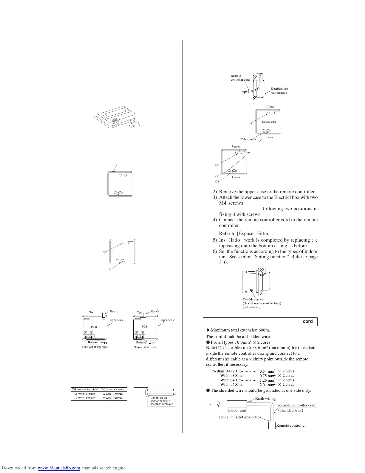
1) Open the remote controller case.
• Put a screw driver (flat-head) into the concavity
made on the upper part of a remote controller and
twist it lightly to open the casing.
2) The cord of a remote controller can only be pulled
out in the upward direction.
• Cut off with nippers or a knife a thin walled part
made on the upper end of the rmote controller
bottom casing, and then remove burrs with a file
or the like.
3) Fix the remote controller bottom casing onto a wall
with two wood screws supplied as accessories.
4) Connect the remote controller cord to the termi-
nal block. Connect between the remote controller
terminals (x, Y) and the indoor unit terminals
(x, Y). (x and Y have no polarity.)
Wiring path will be as shown below depending on
the direction to take out.
• Cord used in the remote controller should be 0.3
mm
2
- max. 0.5 mm
2
. Remove a sheath for the
section laid within the remote controller casing.
The length of each wire that should be left after a
sheath is removed is as follows.
5) Replace the top casing as before.
6) Use a cord clamp to attach the remote controller
cord to the wall.
Thin walled part
Upper
Lower
Lower case
Upper
Lower
Lower case
Precation in extending the remote controller cord
●
!
"
#
$#
#
%& & "
▼
●
' ( )
* + ( #
& ,
,, - . (
/ ,
0
2) Remove the upper case to the remote controller.
3) Attach the lower case to the Electricl box with two
M4 screws. (Head diameter must be 8 mm).
Choose either of the following two positions in
fixing it with screws.
4) Connect the remote controller cord to the remote
controller.
Refer to [Exposed Fitting].
5) Installation work is completed by replacing the
top casing onto the bottom casing as before.
6) Set the functions according to the types of indoor
unit. See section “Setting function”. Refer to page
310.
 Loading...