-
256
-
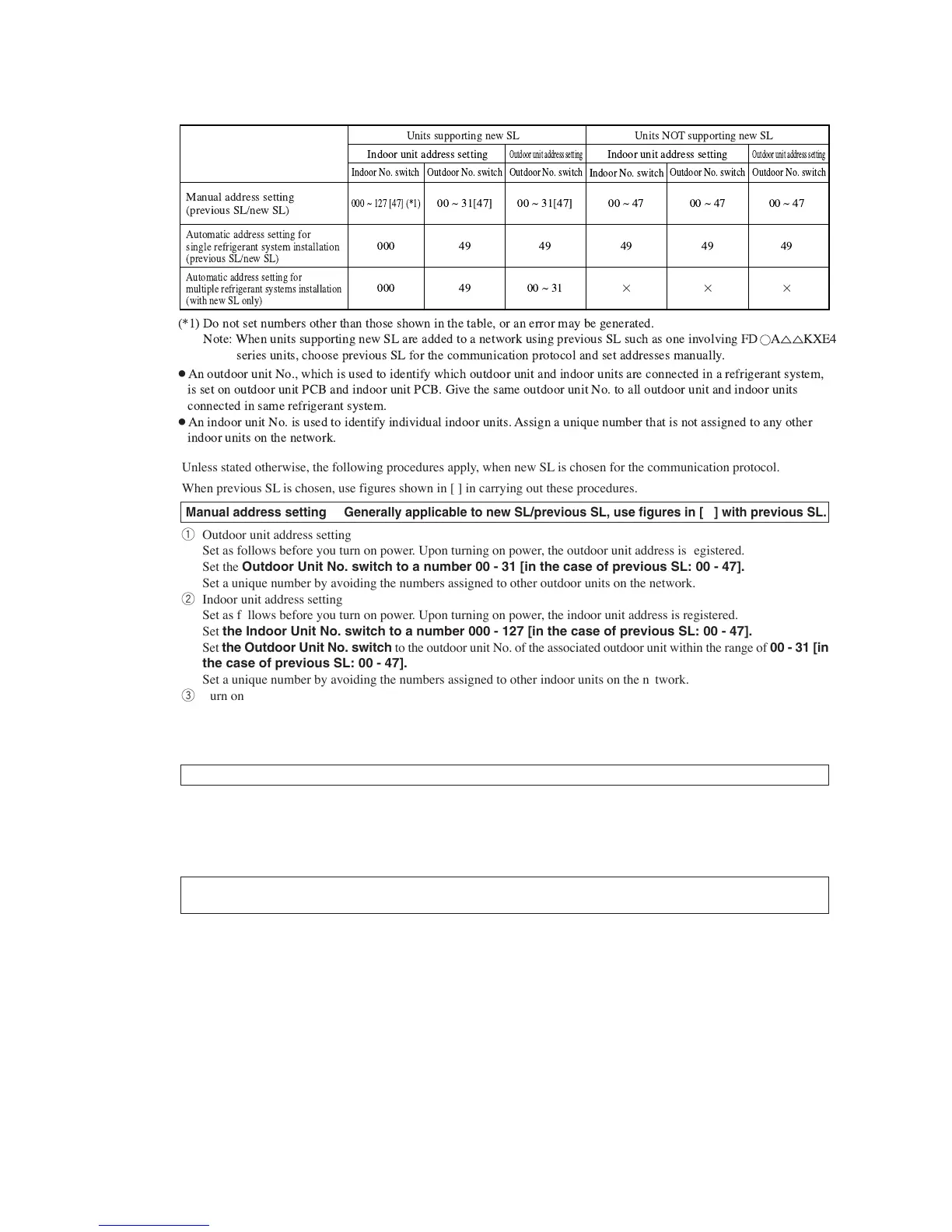
● Summary of address setting methods (figures in [ ] should be used with previous SL)
!
!
!
!
!
!
●
!" "
#$% #$%! & !
!
●
! ! ' (
)!
*+ , ( (" ( !
. / ) 0, 1234
" !
555 6 +78 948: *+
555
555
55 6 ;+948:
4<
4<
55 6 ;+948:
4<
556;+
55648
4<
55648
4<
55648
4<
Unless stated otherwise, the following procedures apply, when new SL is chosen for the communication protocol.
When previous SL is chosen, use figures shown in [ ] in carrying out these procedures.
Manual address setting Generally applicable to new SL/previous SL, use figures in [ ] with previous SL.
q Outdoor unit address setting
Set as follows before you turn on power. Upon turning on power, the outdoor unit address is registered.
Set the Outdoor Unit No. switch to a number 00 - 31 [in the case of previous SL: 00 - 47].
Set a unique number by avoiding the numbers assigned to other outdoor units on the network.
w Indoor unit address setting
Set as follows before you turn on power. Upon turning on power, the indoor unit address is registered.
Set the Indoor Unit No. switch to a number 000 - 127 [in the case of previous SL: 00 - 47].
Set the Outdoor Unit No. switch to the outdoor unit No. of the associated outdoor unit within the range of 00 - 31 [in
the case of previous SL: 00 - 47].
Set a unique number by avoiding the numbers assigned to other indoor units on the network.
e Turn on power in order from the outdoor unit to indoor units. Give a one-minute or longer interval for them.
* When there are some units not supporting new SL connected in the network, set SW5-5 to ON to choose the previous
SL communication mode.
In the case of previous SL, the maximum number of indoor units connectable in a network is 48.
Automatic address setting Generally applicable to new SL/previous SL, use figures in [ ] with previous SL.
With new SL, you can set indoor unit addresses automatically even for an installation involving multiple refrigerant systems
connected with same network, in addition to the conventional automatic address setting of a single refrigerant system instal-
lation.
However, an installation must satisfy some additional requirements such as for wiring methods, so please read this manual
carefully before you carry out automatic address setting.
(1) In the case of a single refrigerant system installation
(Generally applicable to new SL/previous SL, use figures in [ ] with previous SL.)
q Outdoor unit address setting
Set as follows before you turn on power.
Make sure that the Outdoor Unit No. switch is set to 49 (factory setting)
w Indoor unit address setting
Set as follows before you turn on power.
Make sure that the Indoor Unit No. switch is set to 000 [in the case of previous SL: 49] (factory setting)
Make sure that the Outdoor Unit No. switch is set to 49 (factory setting)
e Turn on power in order from the outdoor unit to indoor units. Give a one-minute or longer interval for them. Unlike the
procedure set out in (2) below, you need not change settings from the 7 segment display panel.
r Make sure that the number of indoor units indicated on the 7 segment display panel agrees with the number of the indoor
units that are actually connected to the refrigerant system.
 Loading...