–
365
–
(4) Replacement of PCB at outdoor unit side
(a) Control PCB
Precautions for Safety
• Since the following precaution is the important contents for safety, be sure to observe them.
WARNING and CAUTION are described as follows:
WARNING
Indicates an imminently hazardous situation which will result in death or serious injury if proper
safety procedures and instructions are not adhered to.
CAUTION
Indicates a potentially hazardous situation which may result in minor or moderate injury if proper
safety procedures and instructions are not adhered to.
WARNING
• Securely replace the PCB according to this procedure.
If the PCB is incorrectly replaced, it will cause an electric shock or fire.
• Be sure to check that the power source for the outdoor unit is turned OFF before replacing the PCB. The PCB
replacement under current-carrying will cause an electric shock or fire.
• After finishing the PCB replacement, check that wiring is correctly connected with the PCB before power
distribution. If the PCB is incorrectly replaced, it will cause an electric shock or fire.
CAUTION
• Band the wiring so as not to tense because it will cause an electric shock.
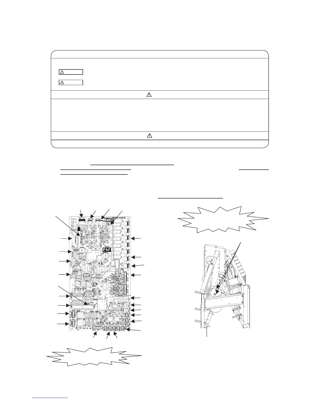
Replacement the control PCB according to the following procedure.
1. Replace the PCB
after elapsing 3 minutes from power OFF.
(Be sure to measure voltage (DC)
on both capacitor terminals located in controller back, and
check that the
voltage is discharged sufficiently
.(Refer to Fig.2))
2. Disconnect the connectors from the control PCB.
3. Disconnect the white wiring passing through CT1 on the PCB before replacing the PCB.
4. Match the setting switches (SW3-5) with the former substrate.
5. Tighten up a screw after passing white wiring through CT1 of the changed.
6. Connect the connectors to the control PCB.(Confirm the
connectors are not half inserted
.)
 Loading...