–
366
–
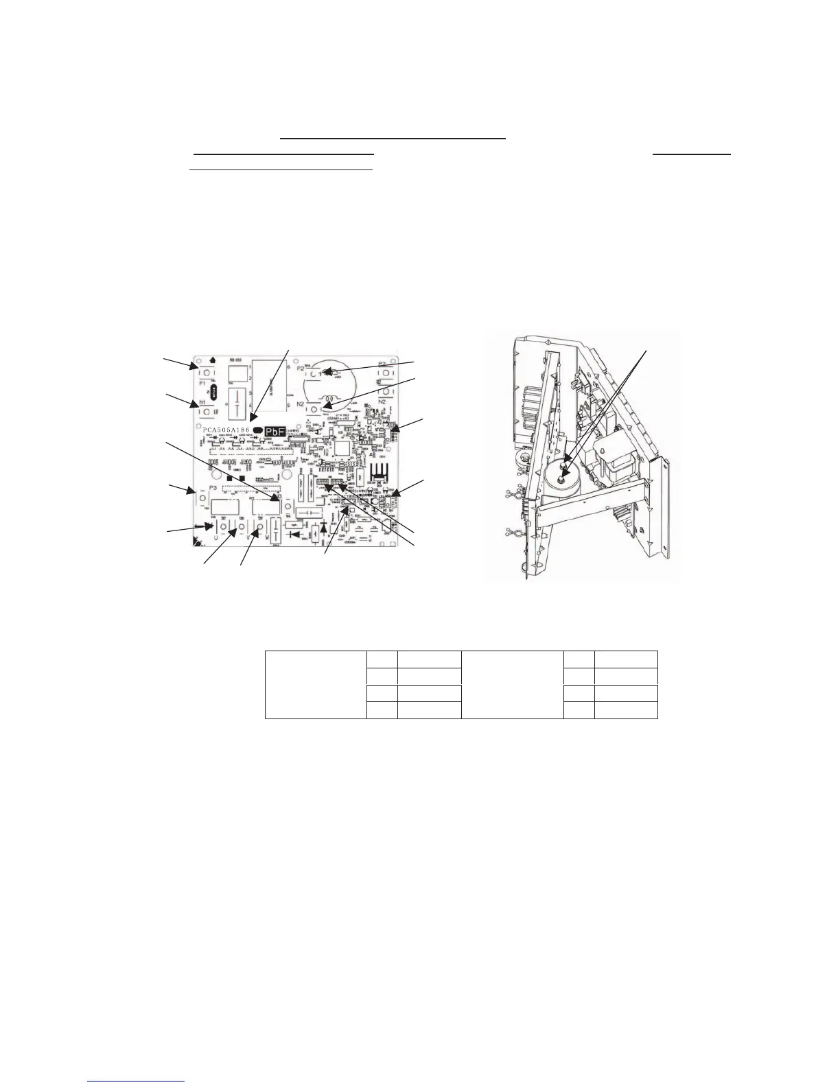
(b) Inverter PCB
1) FDC112, 140, 155KXEN6 model
a) Exchange the PCB
after elapsing 3 minutes from power OFF
.
(
Be sure to measure voltage (DC)
on both capacitor terminals located in controller back, and
check that the
voltage is discharged sufficiently
.(Refer to Fig.2))
b) Take off the connection of inverter PCB terminal block connector and remove the screw of power transistor then
remove the PCB. Wipe off the silicon grease neatly on the controller’s radiation heat fins.
c) Refer to table1 for the setting of switch (JSW10,11) of new PCB.
d) Before installing the power transistor on the new PCB,Apply uniformly a bundled of silicon grease first on the
surface of power transistor.Make sure it is applied to prevent damage on power transistor.
e) Tighten the screw of power transistor on inverter PCB and connect the terminal block.Confirm the connection
and don’t use soldering in the connection.Tighten properly the power transistor with a screw and make sure there
is no slack.Power transistor can be damage if not properly tighten.(Recommended power transistor tightening
torque:0.98~1.47N∙m)
 Loading...