-
245
-
a) On-site piping work
Important
● Please take care so that installed pipes may not touch components within a
unit.
● During the pipe installation at site, keep the service valves shut all
the time.
● Give sufficient protections (compressed and brazed or by an adhesive tape)
to pipe ends so that any water or foreign matters may not enter
the pipes.
● In bending a pipe, bend it to the largest possible radius (at least four times the pipe diameter). Do not bend a
pipe repeatedly to correct its form.
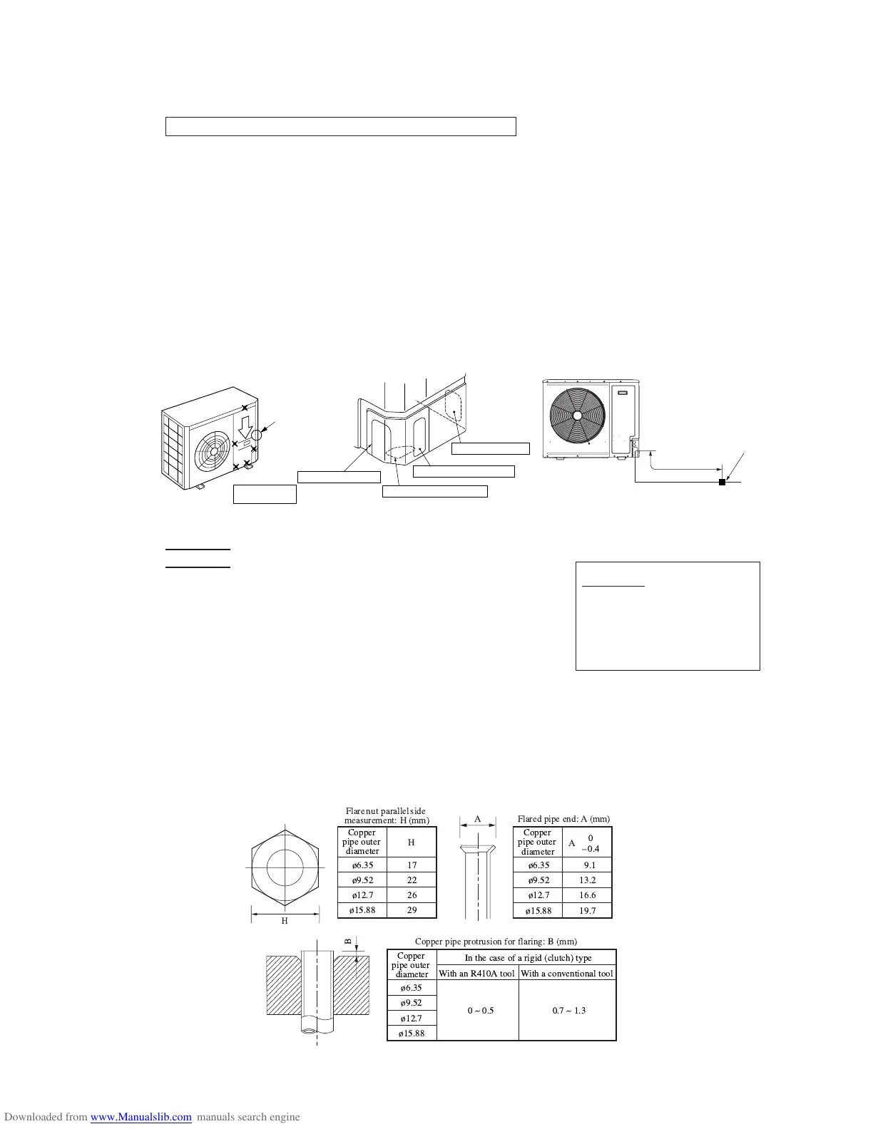
● An outdoor unit’s pipe and refrigerant piping are to be flare connected. Flare a pipe after engaging a flare nut onto it. A
flare size for R410A is different from that for conventional R407C. Although we recommend the use of flaring tools
developed specifically for R410A, conventional flaring tools can also be used by adjusting the measurement of protrusion
B with a protrusion control gauge.
● Tighten a flare joint securely with two spanners. Observe flare nut tightening torque specified in the table below.
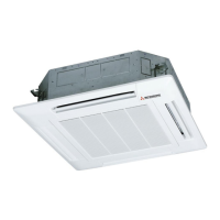
(ii) Piping work
Piping connection position and the piping remove direction
● First remove the five screws ( mark) of the service panel and push it down into the direction of the arrow mark and then
remove it by pulling it toward you.
● The pipe can be laid in any of the following directions: side right, front, rear and downward.
● Remove a knock-out plate provided on the pipe penetration to open a minimum necessary area and attach an edging
material supplied as an accessory by cutting it to an appropriate length before laying a pipe.
● In laying pipes on the installation site, cut off the casing’s half blank that covers a hole for pipe penetration with nippers.
● If there is a risk of small animals entering from the pipe penetration part, close the part with some sealing material or the
like (to be arranged on the installer’s part).
● In the case of an installation using a collective drain system, use a port other than the bottom one to take out cables and
pipes. If the bottom port is used, seal it thoroughly so that drain water may not spill out.
● Use an elbow (to be arranged on the user’s part) to connect control valves to the piping.
● In anchoring piping on the installation site, give 1.5m or a longer distance between an outdoor unit and an anchoring point
where the piping is secured as illustrated below. (A failure to observe this instruction may result in a pipe fracture depending
on a method of isolating vibrations employed.)
Over 1.5m
For front connection
For downward connection
For side right connection
For rear connection
Catch
Outdoor unit
Pipe fastening position
CAUTION
If you tighten it without using
double spanners, you may deform
the service valve, which can cause
an inflow of nitrogen gas into the
outdoor unit.
!
"
#
"$
% & ' ''& (
)& *$" )& '+
"," " ,
!
 Loading...