The backplane has a double lug with two lock nuts on the rear panel where the ground wire connects
to the backplane on one end, and to the rack grounding bar on the other. The rack grounding bar is
connected to the master ground bus bar.
To use the grounding lugs, a length of #6 AWG wire with UL-listed ring lugs is required on both ends.
This wire is shipped with the device.
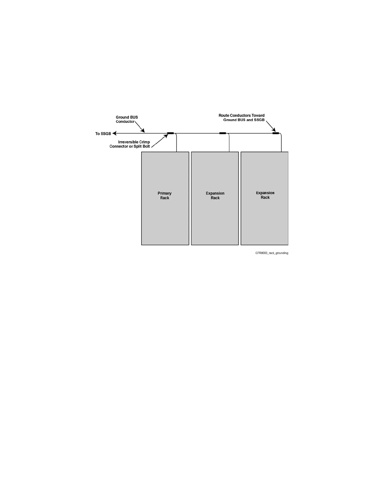
For the cabinet version of the base radio
, the rack grounding bar is connected to the SSGB with a
provided AWG2 dual hole lug.
Figure 41: Rack Grounding
3.4.5.1
Grounding the GTR 8000 Base Radio
Procedure:
1 Connect the ground wire attached to the two grounding lugs at the rear of the base radio to the
rack grounding bar.
2 Tighten the ground lock nut to 60 in-lb (6.94 N.m).
3 Connect all other equipment and peripherals to the rack grounding bar.
3.4.6
GTR 8000 Base Radio Rear Connections (Integrated Voice and Data)
The base radio connects to SITE CTRL ports for this channel and to the transmit and receive paths.
MN003286A01-E
Chapter 3: GTR 8000 Base Radio Installation
105

 Loading...


