Pin No. Signal Type Function Note
40 Aux Out Relay 8
N.O.
Output Main Standby - Antenna Re-
lay
Form Relay A Closed When Active
41 Aux Out Relay 9
N.O.
Output Form Relay A Closed When Active
42 Aux Out Relay 10
N.O.
Output Form Relay A Closed When Active
43 GND GND
44 GND GND
45 RSTAT Output For future use 0 Volts When Inactive / +5 Volts
when Active
46 GND GND
47 TX DATA +
48 GND GND
49 PL + Input PL(+ ) In Analog Signal – 600 Ohm Balanced
50** Gen TX + Input Gen TX DATA + Analog Signal – 600 Ohm Balanced
* For detailed information on the differences between the automatic Fallback In-Cabinet Repeat and
the externally-wired In-Cabinet Repeat functions, see the Conventional Operations manual.
** It is the responsibility of the third-party vendor to ensure that the signal generated by their device is
compliant with any regulatory agency limitation imposed on the channel. This signal is not filtered or
limited by the GTR 8000 Base Radio.
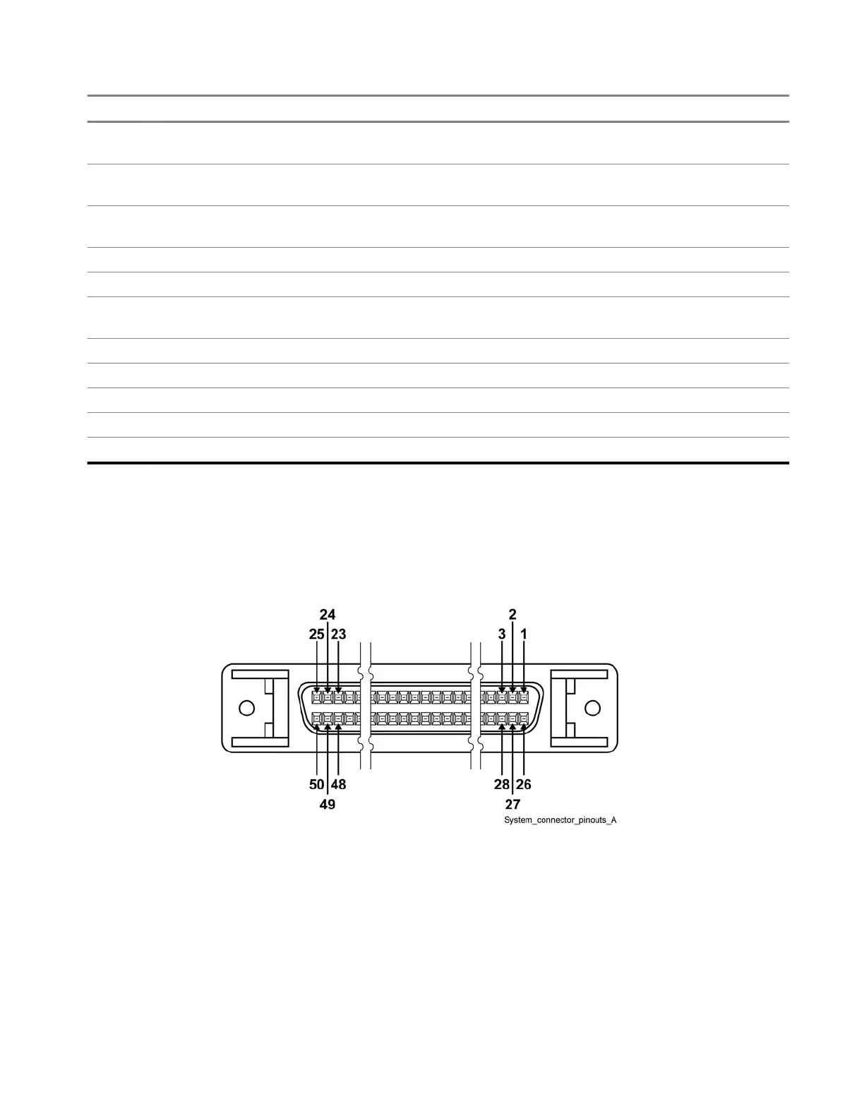
Figure 45: 50–Pin System Connector Pin-Outs (Conventional)
MN003286A01-E
Chapter 3: GTR 8000 Base Radio Installation
114

 Loading...


