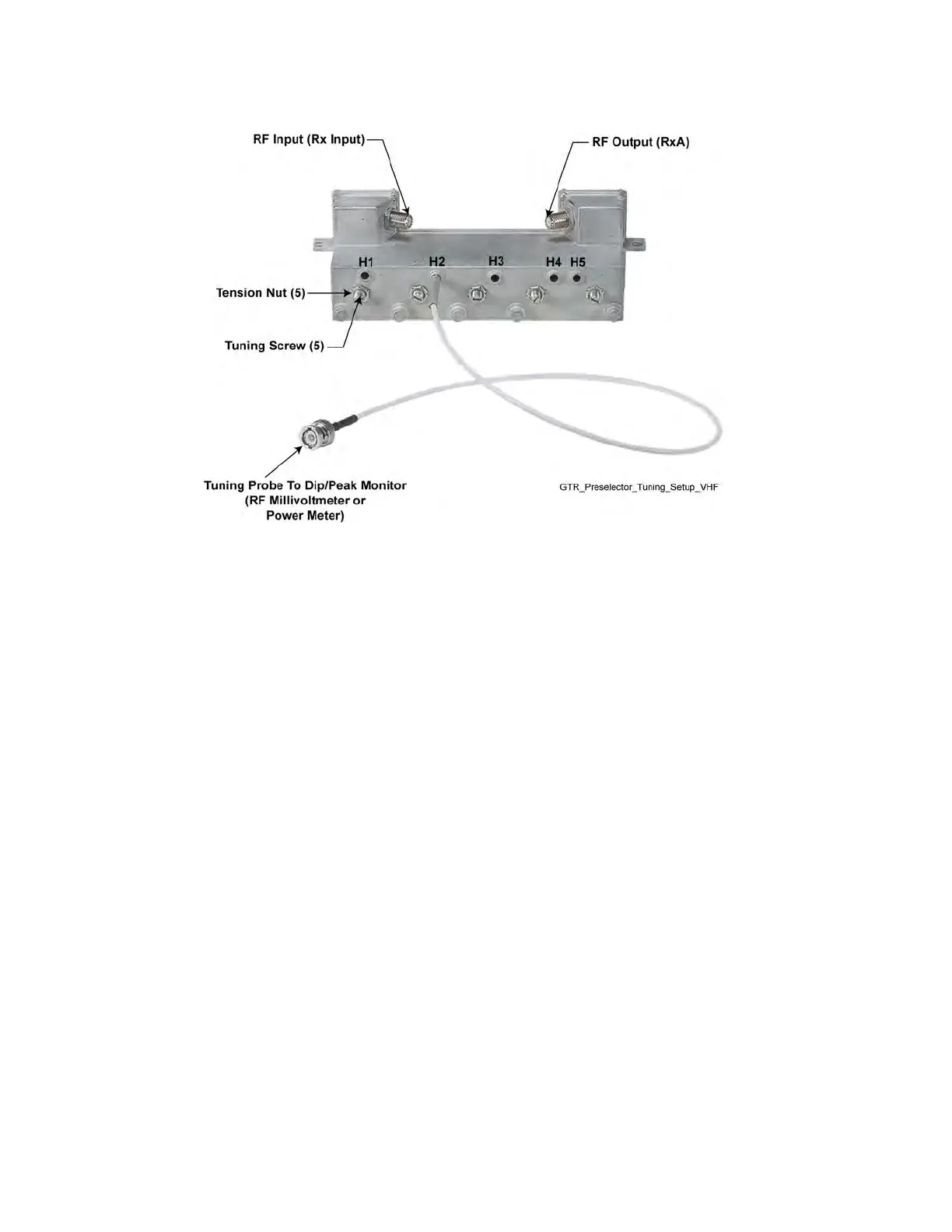
Figure 59: Preselector Tuning — VHF
Procedure:
1 Turn the base radio power supply ON (to provide a 50 Ohm termination).
2 Adjust the signal generator to the frequency calculated in Calculating The VHF Alignment
Frequency For a Single Receive Frequency on page 160 or Calculating The VHF Alignment
Frequency for Multiple Receive Frequencies on page 161. Set the level to +5 dBm.
3 Insert tuning probe into cavity H1 and adjust tuning screw 1 for a PEAK.
4 Leave tuning probe in cavity H1 and adjust tuning screw 2 for a DIP.
5 Insert tuning probe into cavity H2 and adjust tuning screw 3 for a DIP.
6 Insert tuning probe into cavity H3 and adjust tuning screw 4 for a DIP.
7 Insert tuning probe into cavity H4. Decrease output from the signal generator to –5 dBm.
8 Adjust tuning screw 5 for a DIP. Then turn tuning screw 5 an additional 1/4 turn
counterclockwise. (DIP is not as sharp for screw 5 as it was for screws 2 through 4.)
5.9.2
UHF Tuning Procedures
UHF tuning procedures include the following:
• Calculating Proper UHF Alignment Frequency on page 163
• Preparing the Equipment for UHF Alignment on page 164
• Tuning The UHF Preselector on page 164
MN003286A01-E
Chapter 5: GTR 8000 Base Radio Optimization
162

 Loading...


