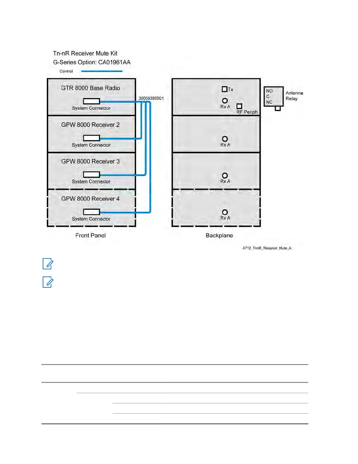
Figure 125: Tn-nR Receiver Mute Option Kit Wiring Diagram
NOTICE: See System Connector Ports (Conventional) on page 112 for a detailed description of
system connector pinouts.
NOTICE: The antenna relay is mounted on the backplane of the GTR 8000 Base Radio. The
only cable used with the Tn-nR Receiver Mute option kit is the control cable. All other required
option kit hardware is included in Table 82: Tn-nR Receiver Mute Option Kit Parts List
on page
290.
A.1.5.1
Tn-nR Receiver Mute Option Kit Parts List
The required hardware and cable for the CA01961AA Tn-nR Receiver Mute option kit are listed in this
section.
Table 82: Tn-nR Receiver Mute Option Kit Parts List
FRU Kit Part Number
Description Quanti-
ty
DLN6798
A
RCVR SOFT NO SPLITTER 1
CKN6944
A
CABLES, RCVR SOFT NO SPLITTER 1
30009380001 CABLE, SAC 1
4210217A04 STRAP TIE .184X7.31 NYL BLK 10
MN003286A01-E
Appendix
A: Conventional GTR 8000 Base Radio Option Kits
290

 Loading...


