c Connect terminator to cavity #6.
5.10.4.8
Checking VHF Duplexer After Tuning
Procedure:
1 Ensure all locking screws are tight.
2 Ensure dust covers on all trimmer capacitors are installed.
3 Ensure all tuning rod locking screws (6) are tight.
5.10.5
Tuning a UHF Duplexer
The following procedures are most easily performed with the duplexer module removed from the rack
or cabinet. Be sure to note the transmit and receive frequencies for the particular base radio before
beginning.
If the duplexer module is tuned according to instructions and does not meet specifications for return
loss, insertion loss, and/or isolation, the duplexer must be returned to the Motorola Solutions Support
Center (SSC) for repair.
5.10.5.1
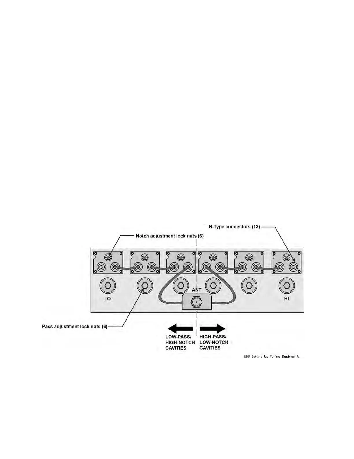
UHF Duplexer Tuning Set Up
Figure 70: UHF Duplexer Tuning Setup
5.10.5.1.1
Setting Up for UHF Duplexer Tuning
Procedure:
1 Disconnect N-type connectors (12) and remove cables (6) from cavities. See Figure 70: UHF
Duplexer Tuning Setup on page 176.
2 For each cavity (6), using an open-end wrench, loosen locknuts (2 per cavity).
MN003286A01-E
Chapter
5: GTR 8000 Base Radio Optimization
176

 Loading...


