CAUTION: To prevent damage to the
base radio, use the HSN1006A speaker with the
0185180U01 cable.
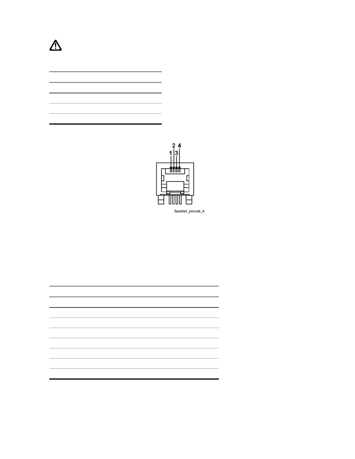
Table 43: Speaker Port Pin-Outs
Signal Name Pin No.
GND 1
+12 V 2
GND 3
Speaker Out 4
Figure 49: Speaker Port Pin-Outs
3.4.8.6
V.24 Port Pin-Outs
The V.24 port is an RJ-45 connector that provides the interface to a Digital Interface Unit, Conventional
Channel Interface, Conventional Channel Gateway (CCGW), ASTRO-TAC
®
3000 Comparator, Link
Converter, or Channel Bank.
Table 44: V.24 Port Pin-Outs
Signal Name Pin No. Type
RCLK 1 Input
Rx Line Det 2 Input
TCLK 3 Input/Output
GND 4 GND
Data Rx 5 Input
Data Tx 6 Output
CTS 7 Input
RTS 8 Output
3.4.8.7
GTR 8000 Base Radio Part 68 Information
This section applies when the
base radio is equipped with the optional wireline interface circuitry
contained on the Oven Controlled Crystal Oscillator (OCXO) Transceiver Option Card (Option
MN003286A01-E
Chapter
3: GTR 8000 Base Radio Installation
119

 Loading...


