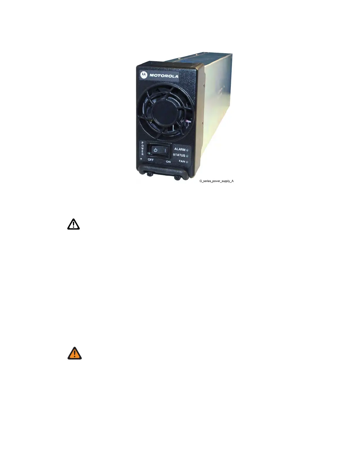
Figure 98: Power Supply
Procedure:
1 Wear an Electrostatic discharge (ESD) wrist strap and connect its cable to a verified good
ground.
CAUTION: Wear The ESD strap throughout this procedure to prevent ESD damage to
any components.
2 For a trunked base radio, place in Service Mode before replacing the module being replaced so
the system does not attribute the loss of channel to a failure.
a Connect to the transceiver module Ethernet service port using CSS. See Connecting
Through an Ethernet Port Link on page 140.
b From the menu, select Service → Test and Measurement Screen.
c Click Change to Service Mode.
d At the confirmation screen, click OK.
The base radio halts activity in the current mode and switches operation to the requested
mode.
3 Push the power rocker switch to Off (O) on the power supply unit.
4 Using a T20 bit, loosen the two captive screws on the front of the power supply to disengage
them from the chassis.
WARNING: Let the power supply module cool before performing the following step which
exposes surfaces of the module that can be hot.
5 Pull on the metal handle to disengage the power supply from the backplane, and remove it
completely from the chassis.
6 Slide the replacement power supply into place, pushing gently until it seats.
7 Using a T20 bit, tighten the two captive screws on the front of the power supply.
8 Turn the power button to On (I), and verify that the power supply is operating properly:
•
The power supply Status LED is green.
• The power supply Alarm LED is off.
MN003286A01-E
Chapter
9: GTR 8000 Base Radio FRU Procedures
239

 Loading...


