d At the confirmation screen, click OK.
The base radio halts activity in the current mode and switches operation to the requested
mode.
4 If you choose to turn off the power, set the rocker switch on the front of the associated power
supply to the Off (O) position.
NOTICE:
It is not necessary to turn off the power supply for the power amplifier module you are
replacing, as the power amplifier modules can be swapped out with the power on.
5 Remove the fan assembly to gain access to the power amplifier module. See Replacing the Fan
Assembly
on page 237 for instructions on removing the fan assembly.
IMPORTANT: The power amplifier module can be swapped out without shutting the
power off. However, minimize the amount of time that the fan is removed, so the circuitry
that remains powered on does not overheat and shut down.
CAUTION: Let the power amplifier module cool before performing the following step
which exposes surfaces of the module that can be extremely hot.
6 Using a T20 bit, loosen the two captive screws on the front of the power amplifier module to
disengage them from the chassis.
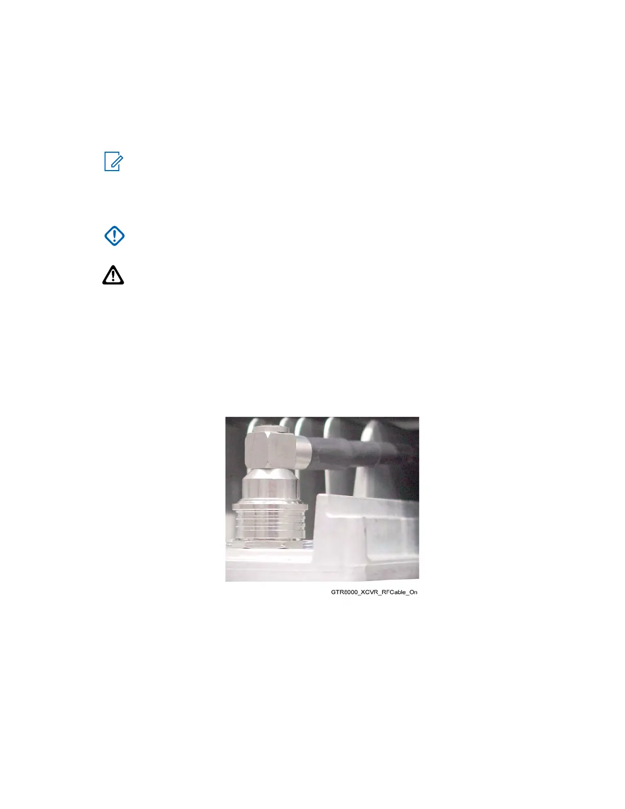
7 Remove the RF output QN connector from the front of the power amplifier module, as follows:
a Pull the power amplifier out of the chassis far enough so that the QN (quick-N) RF output
connector is accessible.
b Disconnect the cable from the power amplifier.
Figure 102: GTR 8000 Power Amplifier RF Cable (Front)
8 Using the handle, gently pull the power amplifier module straight out, along the guides on which
it sits.
9 Reconnect the RF cable to the RF output QN connector on the front of the power amplifier
module, as follows:
a While holding the RF cable, slide in the replacement power amplifier module along the
guiding rails until the RF cable connector can reach the RF connection on the front of the
module.
b Push the RF cables connector on to the module connector until it snaps securely into place.
MN003286A01-E
Chapter
9: GTR 8000 Base Radio FRU Procedures
244

 Loading...


