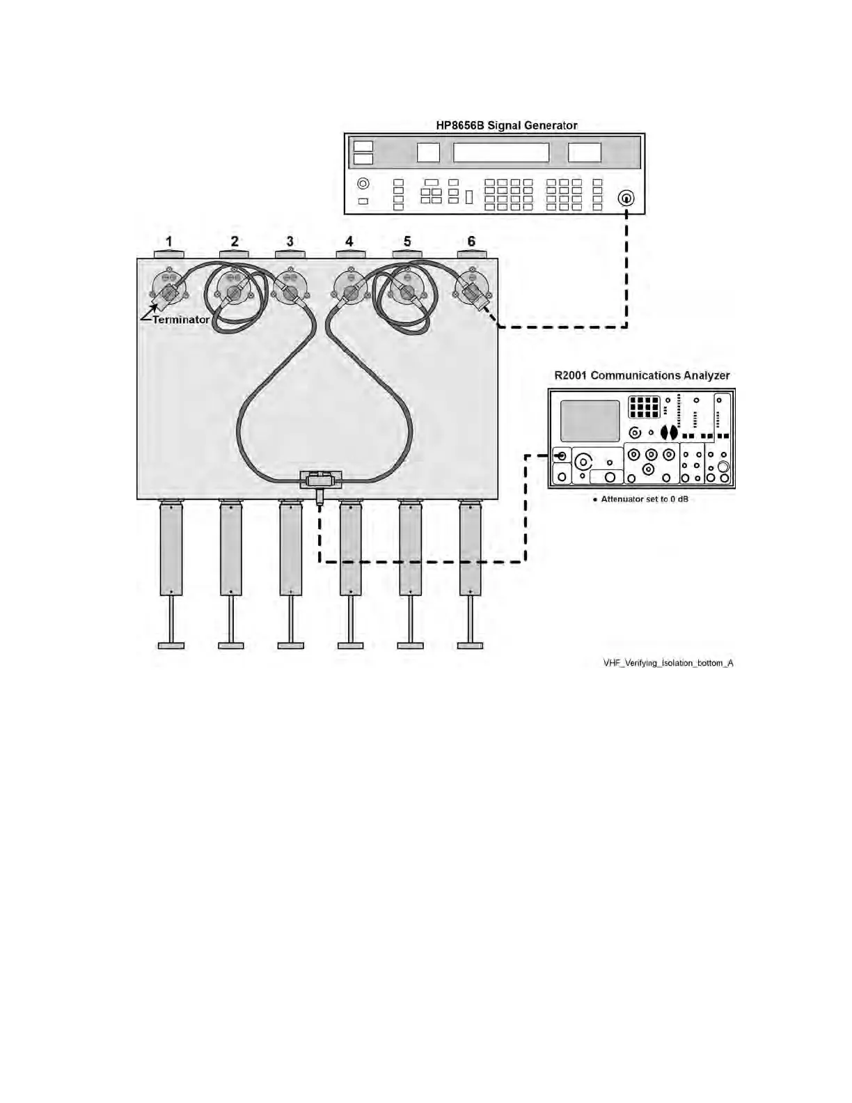
Figure 69: Verifying VHF Duplexer Isolation — Connecting Duplexer Cable Assembly
5.10.4.7.1
Verifying VHF Duplexer Isolation
Procedure:
1 Connect test equipment as shown in Figure 68: Verifying VHF Duplexer Isolation — Connecting
Test Equipment on page 174.
2 Observe and note the level in dBm as shown on the service monitor.
3 Connect the test equipment to the duplexer as shown in Figure 69: Verifying VHF Duplexer
Isolation — Connecting Duplexer Cable Assembly on page 175.
4 Observe and note the level in dBm as shown on the service monitor. (If no number is displayed,
consider isolation to be greater than 105 dB, which exceeds the specification.)
5 Subtract the absolute number noted in step 4 from the number noted in step 2. The difference
should be less than 75 dB to meet specification for isolation.
6 Repeat steps 1 through 5 for Low-Pass/High-Notch cavities with the following exceptions:
a Set service monitor for Rx or Tx frequency, whichever is higher.
b Connect service monitor to Low Pass duplexer input (cavity #1).
MN003286A01-E
Chapter
5: GTR 8000 Base Radio Optimization
175

 Loading...


