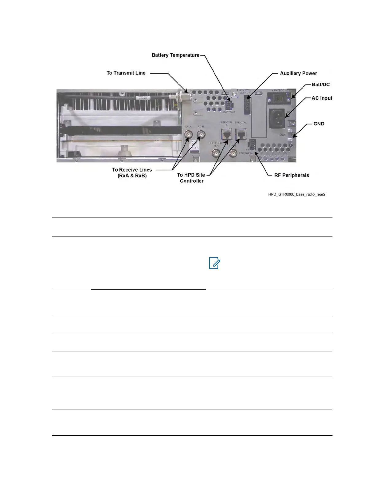
Figure 43: Base Radio – HPD Backplane
Table 37: Base Radio Backplane Connections for HPD
Port /
Type
Device it connects to:
Port /
Type
Description
SC A port,
RJ-45
Site Controller module A Base ra-
dio port,
RJ-45
Connects to site controller A base radio
port for this channel.
NOTICE: The length of the cable
between the site controller and
the base radio should be no
greater than 30 feet.
SC B port,
RJ-45
Site Controller module B Base ra-
dio port,
RJ-45
Connects to site controller B base radio
port for this channel.
RX-A,
BNC
Receive line A BNC RF coax to receive path for Rx antenna.
RX-B,
BNC
Receive line B BNC RF coax to receive path for antenna B.
Transmit
port, N-
type
Transmit line N-type RF coax to transmit antenna.
Aux Pwr
Output
Site Controller or
RMC/LNA
Aux Pwr
Input
The auxiliary output power can be used to
provide secondary power to the site con-
troller or receive multicouplers (Site RMCs/
LNAs).
Bat Temp,
6-pin
Battery temperature sen-
sor
Connection to temperature sensor, allow-
ing for temperature compensated battery
charging.
MN003286A01-E
Chapter
3: GTR 8000 Base Radio Installation
109

 Loading...


