Configuration Examples
361
Insight Managed 8-Port Gigabit Ethernet Smart Cloud Switch with 2 SFP Fiber Ports
kind outside the region. In other words, connectivity within the region is independent of
external connectivity.
MSTP Example Configuration
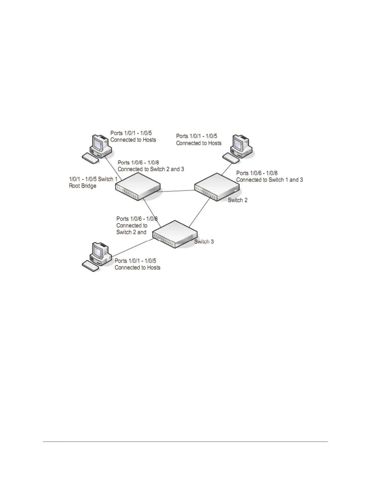
This example shows how to create an MSTP instance from the switch. The example network
includes three different switches that serve different locations in the network. In this example,
ports 1/0/1–1/0/5 are connected to host stations, so those links are not subject to network
loops. Ports 1/0/6–1/0/8 are connected across switches 1, 2, and 3.
Figure 2. MSTP sample configuration
Perform the following procedures on each switch to configure MSTP:
1. On the VLAN Configuration page for each switch, create VLANs 300 and 500 (see Add
a VLAN on page 99).
2. On the VLAN Membership page for each switch,
include ports 1/0/1–1/0/8 as tagged (T) or
untagged (U) members of VLAN 300 and VLAN 500 (see Configure VLAN Membership on
page 103).
3. On the Global Settings page (for STP) for each switch,
enable the Spanning Tree State
option (see Configure STP Settings on page 120).
Use the default values for the rest of the STP configuration settings. By default, the STP
operation mode is MSTP and the configuration name is the switch MAC address.
4. On the CST Configuration page for each switch (see Configure CST Settings on
page 122), set the bridge priority value for each of the three switches to force Switch 1 to be
the root bridge:
• Switch 1. 4096
• Switch 2. 12288
 Loading...