4
Creating a ShopTurn Program 08/2005
4.2 Bases
4
♥ Siemens AG, 2005. All rights reserved
4-128 SINUMERIK 840D sl Operation/Programming ShopTurn (BAT) – 08/2005 Edition
4.2.2 Approaching/retracting in the machining cycle
Approaching and retracting during the machining cycle always follows
the same pattern if you have not defined a special approach/retraction
cycle (see Sec. "Programming the approach/retraction cycle"). If the
machine has a tailstock, you can also take it into consideration when
traversing.
The retraction for a cycle ends at the safety distance. Only the
subsequent cycle moves to the retraction plane. This allows the use of
the special approach/retraction cycle (see Sec. "Programming the
approach/retraction cycle").
During the choosing of the traversing path, ShopTurn always
considers the tool tip, i.e. the elongation of the tool is not taken into
consideration. Be careful therefore that the retraction planes are
correspondingly far away from the workpiece.
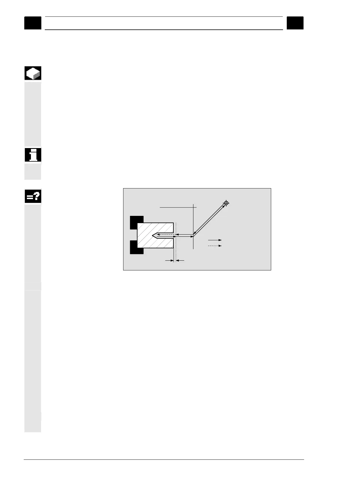
Safety distance
Retract plane
Tool change point
Rapid traverse
Machining feedrate
Approach/retraction of machining cycle
The tool travels in rapid traverse along the shortest path from the
tool change point to the retraction plane which runs parallel to the
machining plane.
After this, the tool travels in rapid traverse to the safety distance.
Then the machining of the workpiece takes place with the
programmed machining feedrate.
After the machining, the tool retracts vertically in rapid traverse to
the safety distance.
Then the tool continues to travel vertically in rapid traverse to the
retraction plane.
From there, the tool travels in rapid traverse along the shortest
path to the tool change point.
If the tool does not need to be changed between two machining
processes, the tool travels from the retraction plane to the next
machining cycle.
The spindle (main, tool, or counter-spindle) begins to rotate
immediately after the tool change.
 Loading...


