2
Setting Up the Machine 08/2005
2.5 Tools
2
♥ Siemens AG, 2005. All rights reserved
2-54 SINUMERIK 840D sl Operation/Programming ShopTurn (BAT) – 08/2005 Edition
2.5 Tools
The various tool geometry parameters must be referenced while the
program is running. These are entered in the tool list as so-called tool
offset data. For each call-up of a tool, the controller takes the tool
offset data into consideration.
When programming therefore, you only have to enter the workpiece
dimensions from the finishing drawing. After this, the controller
independently calculates the individual tool path.
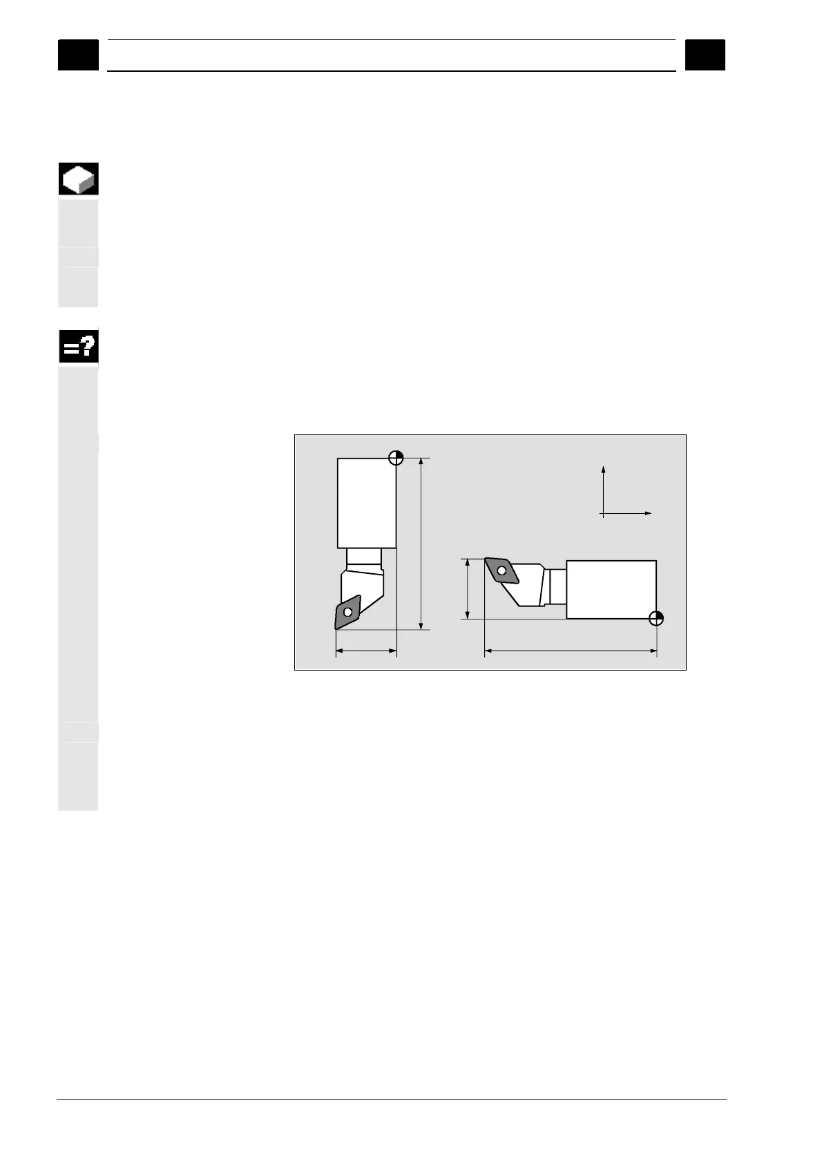
Tool length offset
The tool length offset compensates for the length differences between
the various tools in the X and Z direction.
The tool length is the distance between the tool-carrier reference point
T and tool tip P. If the tool is tensioned in the revolver for a new
machining direction, other tool length offsets will result.
T
T
Length Z
Length Z
Length X
Length X
P
P
X
Z
Tool length offsets
You can determine the tool length offset using the "Measure tool"
function or manually with calipers or a magnifying glass.
The control calculates the traversing movements from the tool length
offset and wear values (see Sec. "Entering Tool Wear Data").
 Loading...


