TRANSMISSION AND CRANKSHAFT 10-13
NOTE:
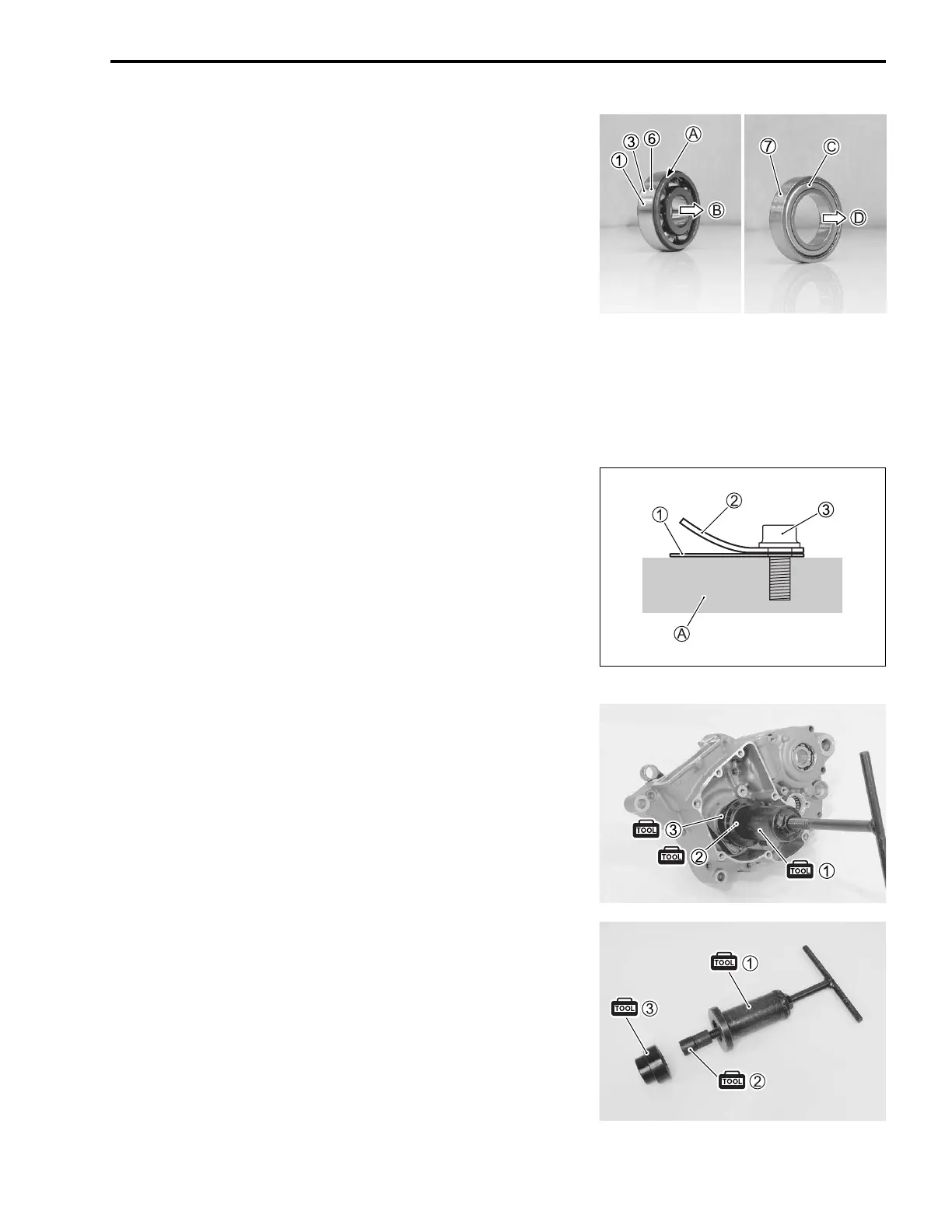
* Press the bearings (1, 3, 6) into the crankcase, so that the
stepped side A faces inside of the crankcase.
* Press the bearing 7 into the crankcase, so that the sealed
side C faces outside of the crankcase.
B Inside of the crankcase
D Outside of the crankcase
• Apply THREAD LOCK SUPER to the bearing retainer screws.
99000-32030: THREAD LOCK SUPER “1303”
or equivalent
• Tighten the bearing retainer screws to the specified torque.
Bearing retainer screw: 8.5 N·m (0.85 kgf-m, 6.0 lbf-ft)
CRANKCASE REED VALVE INSTALLATION
• Install the crankcase reed valve 1 and reed valve guide 2
direction as shown.
• Tighten the reed valve guide bolts 3 to the specified torque.
Reed valve guide bolt: 4.5 N·m (0.45 kgf-m, 3.0 lbf-ft)
A Crankcase
CRANKSHAFT INSTALLATION
• Fit the crankshaft into the left crankcase with the special tools.
NOTE:
Use the attachment (inner driver attachment 3) for crankshaft
bearing inside diameter.
09910-32812: Crankshaft installer 1
09911-11310: Crankshaft installer attachment C 2
09913-70210: Bearing installer set (10 – 75 )
(Inner driver attachment 30 mm 3)

 Loading...


