FI SYSTEM DIAGNOSIS 12-39
“17” (P0105-H/L) IAP SENSOR CIRCUIT MALFUNCTION
NOTE:
After repairing the trouble, clear the DTC using SDS tool. (12-21)
INSPECTION
Step 1 (When indicating 17:)
1) Stop the engine.
2) Check the IAP sensor coupler 1 for loose or poor contacts.
If OK, then measure the IAP sensor input voltage.
3) Disconnect the IAP sensor coupler 1.
DETECTED CONDITION POSSIBLE CAUSE
17
IAP sensor voltage is not within the fol-
lowing range.
0.23 V Sensor voltage < 4.11 V
NOTE:
Note that atmospheric pressure varies
depending on weather conditions as
well as altitude.
Take that into consideration when
inspecting voltage.
• Clogged vacuum passage between throttle body
and IAP sensor.
• Air being drawn from vacuum passage between
throttle body and IAP sensor.
• IAP sensor circuit open or shorted to ground.
• IAP sensor malfunction.
• ECM malfunction.
P0105
H
Sensor voltage is higher than specified
value.
• IAP sensor circuit shorted to VCC or ground cir-
cuit open.
• IAP sensor circuit open or shorted to ground or
VCC circuit open.
L
Sensor voltage is lower than specified
value.
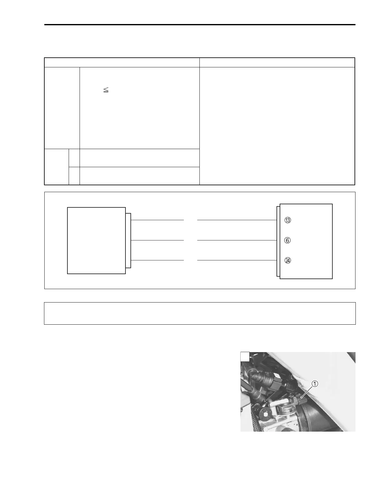
ECM
VCC
IAP
E2
IAP sensor
B/Br
R/Bl
G/B
When using the multi circuit tester, do not strongly touch the terminal of the ECM coupler with
a needle-pointed tester probe to prevent the terminal damage or terminal bend.
1

 Loading...


