11-6 LUBRICATION SYSTEM
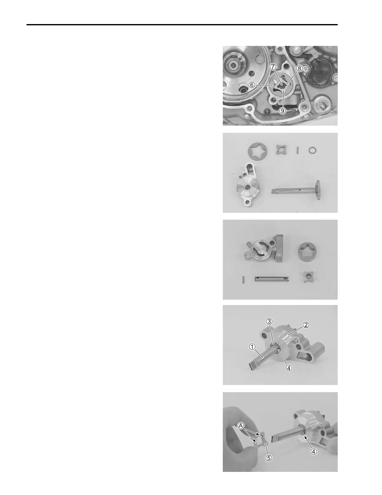
• Remove the outer rotor 6, oil pump No.2 shaft 7, pin 8 and
inner rotor 9.
OIL PUMP No.1 AND No.2 INSPECTION
• Check the oil pump with each part for any defects or wear.
• If necessary, replace the defective parts with a new one.
OIL PUMP No.1 AND No.2 INSTALLATION
OIL PUMP No.1
Install the oil pump No.1 in the reverse order of removal. Pay
attention to the following points:
• Install the oil pump No.1 cover 2, washer 3 and pin 4 onto
the oil pump driven gear shaft 1.
• Fit the slot A of the inner rotor 5 onto the pin 4.

 Loading...


