12-16 FI SYSTEM DIAGNOSIS
SELF-DIAGNOSIS FUNCTION
The self-diagnosis function is incorporated in the ECM. It can be notified by using the FI indicator light assy
(option). To check the function of the individual FI system devices, the dealer mode is provided. In this
check, the tool is necessary to read the DTC (Diagnostic Trouble Code) that identify malfunction location.
DEALER MODE
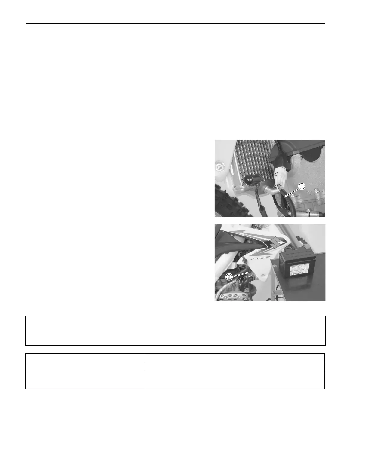
Connect the FI indicator light assy 1 to the mode select coupler. Also, connect a 12 volt battery to the ser-
vice coupler using the battery lead wire 2. The DTC is displayed by flashing pattern of FI indicator light. This
means that the ECM has not received signals indicating a correct condition from the sensors or device con-
cerned.
36380-28H00: FI indicator light assy (option)
36890-28H00: Battery lead wire (option)
NOTE:
The FI indicator light turns ON for about 2 seconds after connecting the battery.
Before checking the DTC, do not disconnect the ECM lead wire coupler.
If the coupler from the ECM is disconnected, the DTC is erased and the DTC can not be
checked.
MALFUNCTION FI INDICATOR LIGHT INDICATION
“NO” FI indicator light turns OFF.
“YES”
FI indicator light turns ON and blinks.
(Code is indicated from small numeral to large one.)

 Loading...


