FI SYSTEM DIAGNOSIS 12-31
“14” (P0120-H/L) TP SENSOR CIRCUIT MALFUNCTION
NOTE:
After repairing the trouble, clear the DTC using SDS tool. (12-21)
INSPECTION
Step 1 (When indicating 14:)
1) Stop the engine.
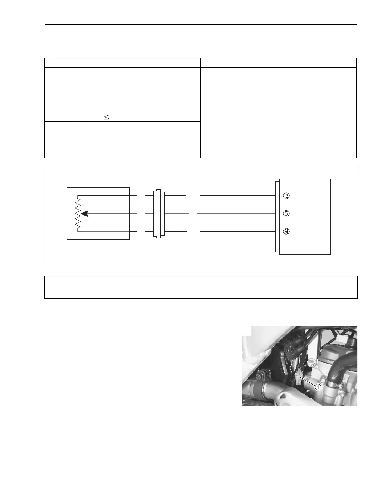
2) Check the TP sensor coupler 1 for loose or poor contacts.
If OK, then measure the TP sensor input voltage.
3) Disconnect the TP sensor coupler 1.
4) Connect a 12 volts battery by using the battery lead wire to
the service coupler. (12-19)
DETECTED CONDITION POSSIBLE CAUSE
14
Output voltage is not within the following
range.
Difference between actual throttle open-
ing and opening calculated by ECM is
larger than specified value.
0.39 V Sensor voltage < 4.51 V
• TP sensor maladjusted.
• TP sensor circuit open or short.
• TP sensor malfunction.
• ECM malfunction.
P0120
H
Sensor voltage is higher than specified
value.
• TP sensor circuit shorted to VCC or ground circuit
open.
• TP sensor circuit open or shorted to ground or
VCC circuit open.
L
Sensor voltage is lower than specified
value.
ECM
R/Bl
B/Br
VCC
TP
E2
TP sensor
Y
Bl
Y
B
When using the multi circuit tester, do not strongly touch the terminal of the ECM coupler with
a needle-pointed tester probe to prevent the terminal damage or terminal bend.
1

 Loading...


