12-52 FI SYSTEM DIAGNOSIS
“31” (P0705) GP SWITCH CIRCUIT MALFUNCTION
NOTE:
After repairing the trouble, clear the DTC using SDS tool. (12-21)
INSPECTION
Step 1
1) Stop the engine.
2) Remove the fuel tank. (13-2, -3)
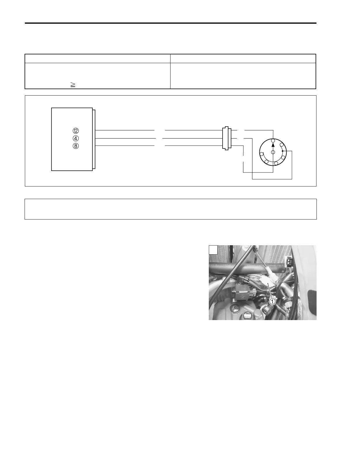
3) Check the GP switch coupler 1 for loose or poor contacts.
If OK, then measure the GP switch voltage.
DETECTED CONDITION POSSIBLE CAUSE
No GP switch voltage
Switch voltage is not within the following range.
Switch voltage 0.89 V
• GP switch circuit open or short.
• GP switch malfunction.
• ECM malfunction.
N
1
5
4
2
3
ECM
GP switch
BI
P
B/W
B/W
Bl/B
GP
NT
E1
P
When using the multi circuit tester, do not strongly touch the terminal of the ECM coupler with
a needle-pointed tester probe to prevent the terminal damage or terminal bend.
1

 Loading...


