12-4 FI SYSTEM DIAGNOSIS
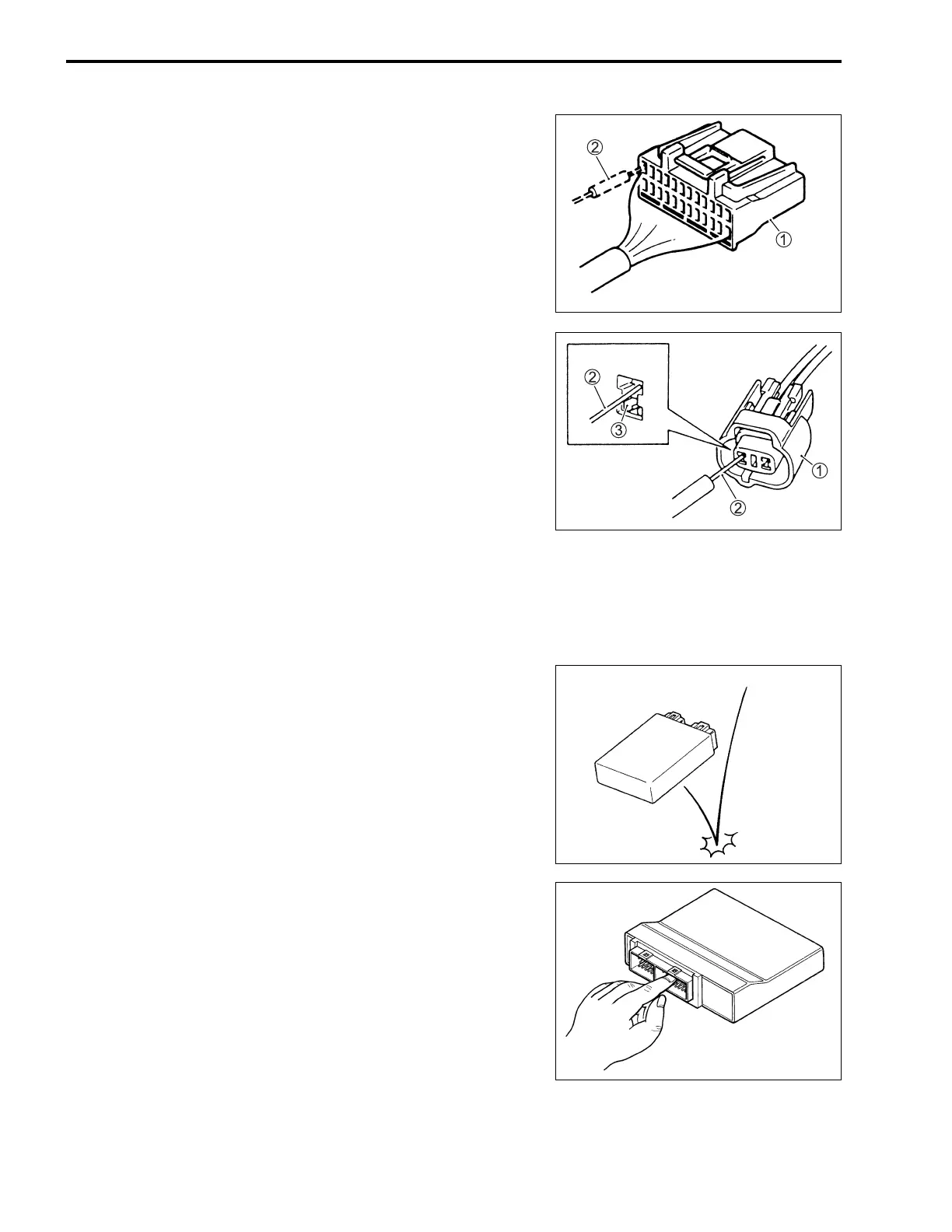
• When taking measurements at electrical connectors using a
tester probe, be sure to insert the probe from the wire harness
side (backside) of the connector/coupler.
1 Coupler
2 Probe
• When connecting meter probe from the terminal side of the
coupler (where connection from harness side not being possi-
ble), use extra care not to force and cause the male terminal
to bend or the female terminal to open.
Connect the probe as shown to avoid opening of female ter-
minal.
Never push in the probe where male terminal is supposed to
fit.
• Check the male connector for bend and female connector for
excessive opening. Also check the coupler for locking (loose-
ness), corrosion, dust, etc.
1 Coupler
2 Probe
3 Where male terminal fits
ECM/VARIOUS SENSORS
• Since each component is a high-precision part, great care
should be taken not to apply any sharp impacts during
removal and installation.
• Be careful not to touch the electrical terminals of the ECM.
The static electricity from your body may damage this part.
INCORRECT

 Loading...


