15-8 ELECTRICAL SYSTEM
GENERATING SYSTEM
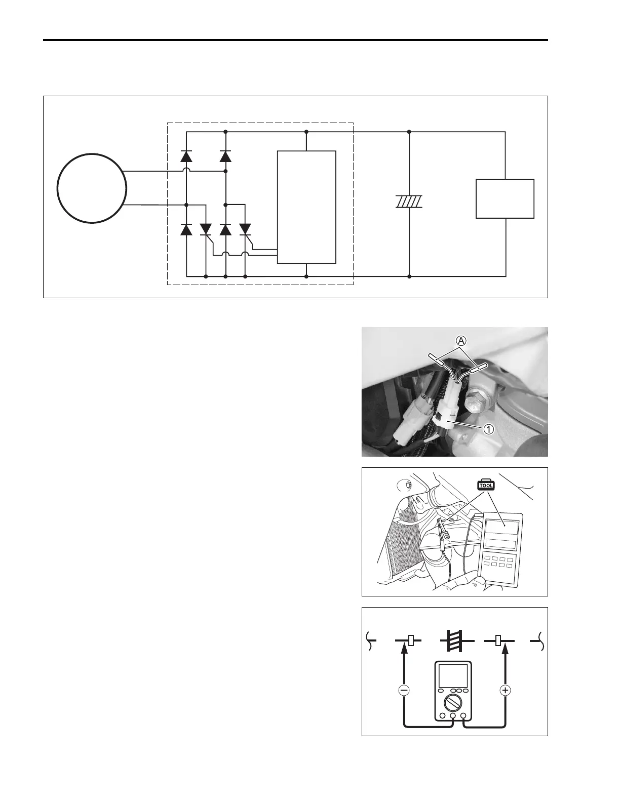
INSPECTION
REGULATED VOLTAGE
• Insert the needle-point probes A to the condenser coupler 1.
+ Prove: Red lead wire
- Prove: B/W lead wire
• Kickstart the engine.
• Insert the needle-pointed probe to the lead wire coupler (W/
Bl).
• Connect the engine tachometer to the needle-pointed probe.
• Kickstart the engine and keep the engine running at 5 000 r/
min.
• Measure the DC voltage using the multi circuit tester. If the
voltage is not within the specified value, inspect the magneto
and regulator/rectifier. (15-9, -10)
Regulated voltage (Charging output):
14.0 – 15.0 V at 5 000 r/min
09900-25008: Multi circuit tester set
09900-25009: Needle-point probe set
09900-26006: Engine tachometer
Tester knob indication: Voltage ()
Magneto
Regulator/Rectifier
SCR
IC
Load
Condenser
Condenser
DCV
B/W
B/W
O
B/R

 Loading...


