ELECTRICAL SYSTEM 15-9
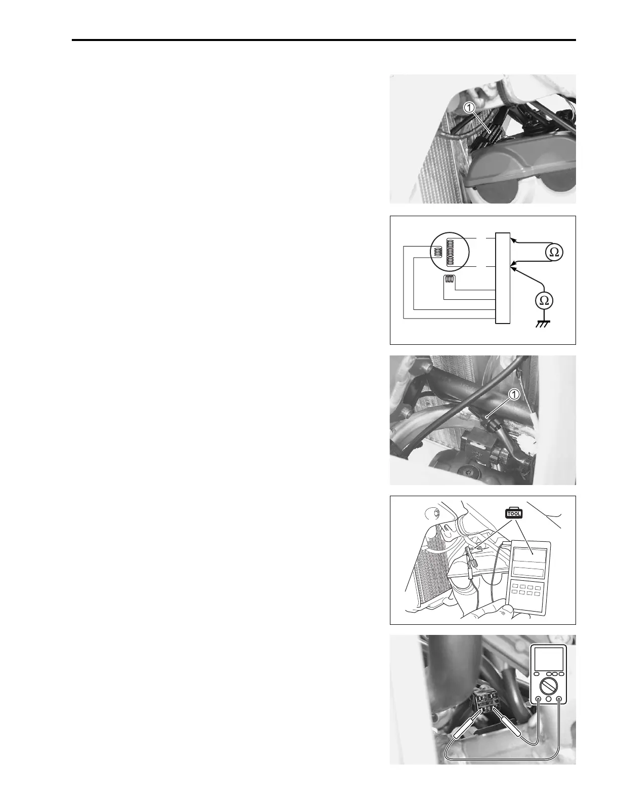
CHARGE COIL RESISTANCE
• Disconnect the magneto lead wire coupler 1.
• Measure the charge coil resistance.
If the resistance is out of specified value, replace the stator
with a new one. Also, check that the magneto core is insu-
lated properly.
Charge coil resistance:
1.0 – 2.5
Ω
(Yellow – Yellow)
∞ Ω (
Yellow
– Ground)
09900-25008: Multi circuit tester set
Tester knob indication: Resistance (Ω)
NOTE:
When making above test, it is not necessary to remove the mag-
neto.
MAGNETO NO-LOAD PERFORMANCE
• Lift and hold the fuel tank. (13-4)
• Disconnect the regulator/rectifier coupler 1.
• Connect a 12 volt battery to the service coupler using the bat-
tery lead wire (optional part). (12-19)
• Insert the needle-pointed probe to the lead wire coupler (W/
Bl).
• Connect the engine tachometer to the needle-pointed probe.
• Kickstart the engine and keep the engine running at 5 000 r/
min.
• Measure the AC voltage using the multi circuit tester. If the
tester reads under the specified value, replace the magneto
with a new one.
Magneto no-load performance (When engine is cold):
95 V and more at 5 000 r/min (
Yellow
–
Yellow
)
09900-25008: Multi circuit tester set
36890-28H00: Battery lead wire (option)
09900-26006: Engine tachometer
Tester knob indication: Voltage (~)
Y
Y
ACV