LUBRICATION SYSTEM 11-7
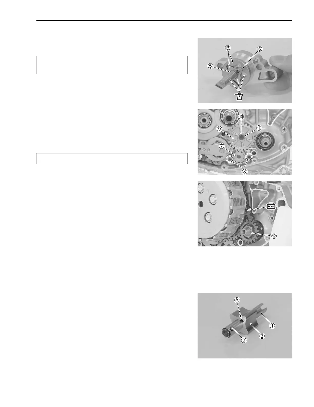
• Install the outer rotor 6.
• Apply engine oil to the oil pump driven gear shaft, outer rotor
and inner rotor.
• Install the oil pump No.1 7 and tighten the oil pump No.1
bolts 8 to the specified torque.
Oil pump No.1 bolt: 5.5 N·m (0.55 kgf-m, 4.0 lbf-ft)
• Install the oil pump idle gear 9, washer 0 and snap ring A.
09900-06107: Snap ring remover (Open type)
• Install the primary drive gear. (10-18)
• Install the clutch component parts. (7-6, -7, -9, -10)
• Apply THREAD LOCK SUPER to the primary drive gear nut
B.
99000-32110: THREAD LOCK SUPER “1322”
or equivalent
• Hold the crankshaft immovable with the special tool and
tighten the primary drive gear nut B to the specified torque.
09914-61010: Gear holder
Primary drive gear nut: 90 N·m (9.0 kgf-m, 65.0 lbf-ft)
• Install the right crankcase cover and kick starter lever.
(8-7, -8)
• Install the brake pedal. (17-20)
OIL PUMP No.2
Install the oil pump No.2 in the reverse order of removal. Pay
attention to the following points:
• Install the pin 2 into the oil pump No.2 shaft 1.
• Install the inner rotor 3 onto the oil pump No.2 shaft 1.
NOTE:
Fit the slot A of the inner rotor onto the pin 2.
Face the punch mark B on inner rotor 5 outer rotor 6
to the crankcase.
Replace the snap ring with a new one.