12-50 FI SYSTEM DIAGNOSIS
Step 1 (When indicating P1651-L:)
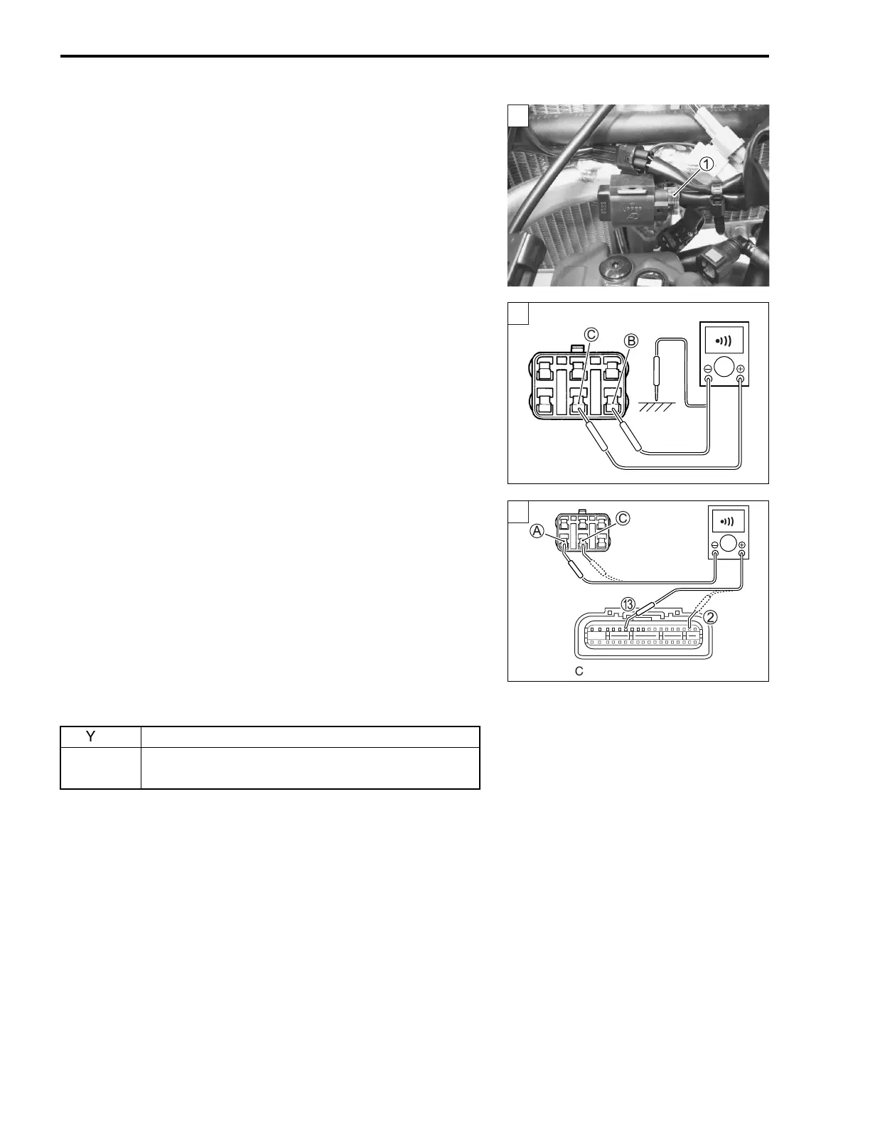
1) Stop the engine.
2) Remove the fuel tank. (13-2, -3)
3) Check the TO sensor coupler 1 for loose or poor contacts.
If OK, then check the TO sensor lead wire continuity.
4) Disconnect the TO sensor coupler and ECM coupler.
5) Check the continuity between Br/W wire C and ground.
6) Also, check the continuity between Br/W wire C and B/Br
wire B. If the sound is not heard from the tester, the circuit
condition is OK.
7) Insert the needle-pointed probes to the lead wire coupler.
8) Check the continuity between R/Bl wire A and terminal C.
9) Also, then check the continuity between Br/W wire C and ter-
minal 2.
TO sensor lead wire continuity: Continuity ()
09900-25008: Multi circuit tester set
09900-25009: Needle-pointed probe set
Tester knob indication: Continuity test ()
Is the continuity OK?
1
1
]
YES Go to Step 2.
NO
R/Bl or Br/W wire open, or Br/W wire shorted to
ground.
1
]
ECM coupler (Harness side)

 Loading...


