EasyManua.ls Logo

ABB ACS560 User Manual

ABB ACS560
514 pages
To Next Page IconTo Next Page
To Previous Page IconTo Previous Page
Page #170 background imageLoading...
Page #170 background image
170 Parameters
04.40 Event word 1 Shows the user-defined event word. This word collects the
status of the events (warnings, faults or pure events) selected
by parameters 04.4104.71.
This parameter is read-only.
-
0000h…FFFFh User-defined event word. 1 = 1
04.41 Event word 1 bit 0
code
Selects the hexadecimal code of an event (warning, fault or
pure event) whose status is shown as bit 0 of 04.40 Event
word 1. The event codes are listed in chapter Fault tracing
(page 409).
0x2310h
0000h…FFFFh Code of event. 1 = 1
04.43 Event word 1 bit 1
code
Selects the hexadecimal code of an event (warning, fault or
pure event) whose status is shown as bit 1 of 04.40 Event
word 1. The event codes are listed in chapter Fault tracing
(page 409).
0x3210h
0000h…FFFFh Code of event. 1 = 1
04.45,
04,47,
04,49,
……
04.71 Event word 1 bit 15
code
Selects the hexadecimal code of an event (warning, fault or
pure event) whose status is shown as bit 15 of 04.40 Event
word 1. The event codes are listed in chapter Fault tracing
(page 409).
0x2330h
0000h…FFFFh Code of event. 1 = 1
05
05 Diagnostics
Various run-time-type counters and measurements related to
drive maintenance.
All parameters in this group are read-only unless otherwise
noted.
05.01 On-time counter On-time counter. The counter runs when the drive is
powered.
0
0…65535 d On-time counter. 1 = 1 d
05.02 Run-time counter Motor run-time counter. The counter runs when the inverter
modulates.
0
0…65535 d Motor run-time counter. 1 = 1 d
05.03 Hours run Corresponding parameter to 05.02 Run-time counter in
hours, that is, 24 * 05.02 value + fractional part of a day.
-
0.0
429496729.5 h
Hours. 1 = 1 h
05.04 Fan on-time
counter
Running time of the drive cooling fan. Can be reset from the
control panel by keeping Reset down for over 3 seconds.
0
0…65535 d Cooling fan run-time counter. 1 = 1 d
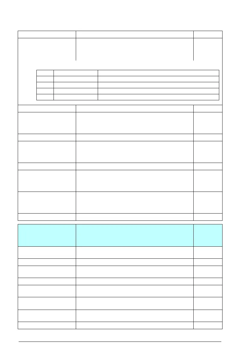
No. Name/Value Description Def/FbEq16
Bit Name Description
0 User bit 0 1 = Event selected by parameter 04.41 is active
1 User bit 1 1 = Event selected by parameter 04.43 is active
……
15 User bit 15 1 = Event selected by parameter 04.71 is active

Table of Contents

Other manuals for ABB ACS560

Question and Answer IconNeed help?

Do you have a question about the ABB ACS560 and is the answer not in the manual?

ABB ACS560 Specifications

General IconGeneral
Frequency50/60 Hz
Control MethodScalar control
Protection FeaturesOvercurrent, overvoltage, undervoltage, short circuit
Communication InterfacesModbus RTU, Profibus DP, CANopen, Ethernet/IP
Enclosure RatingIP21
Ambient Temperature-10 to +50 °C
Input Voltage380 to 480 V AC
Cooling MethodAir cooling (natural convection or forced ventilation)

Summary

Introduction to the Manual

Safety instructions

Outlines safety precautions and references to the hardware manual for detailed instructions.

Start-up, Control with I/O and ID run

How to start up the drive

Details the process of starting up the drive, including safety and general information for basic control panel use.

How to control the drive through the I/O interface

Explains how to operate the drive using digital and analog inputs for start/stop, direction, and speed control.

Identification (ID) run

Describes the drive's process of identifying motor characteristics for optimal motor control.

ID run procedure

Provides a step-by-step guide on how to perform the ID run manually, including pre-checks.

Program features

Drive configuration and programming

Covers the main control functions including speed, torque, frequency control, and drive logic configuration.

Speed controller autotune

Details how the drive's speed controller can be automatically adjusted using the autotune function.

Process PID control

Explains the use of built-in process PID controllers for controlling variables like pressure or flow.

Mechanical brake control

Describes the logic and states involved in controlling a mechanical brake for holding the motor at zero speed.

Control macros

ABB standard macro

Details the default macro features, including 2-wire I/O configuration and scalar control by default.

ABB standard macro (vector)

Describes the vector control variant of the ABB standard macro, similar to the standard macro but using vector control.

PID macro

Describes the PID macro suitable for applications where the drive is always controlled by PID with reference from analog input AI1.

Torque control macro

Covers the torque control macro for applications requiring torque control, typically for tension applications.

Parameters

Parameter listing

Presents a detailed list of parameters, including their numbers, names, descriptions, and default/FbEq16 values.

Fault tracing

Fieldbus control through the embedded fieldbus interface (EFB)

Setting up the embedded fieldbus interface

Guides on configuring parameters for automatic setup and manual configuration of the embedded fieldbus interface.

Fieldbus control through a fieldbus adapter

Control chain diagrams

Speed controller

Presents a block diagram of the speed controller, showing proportional, integral, and derivative actions.

Process PID controller

Illustrates the PID controller block diagram, including setpoint, feedback, and output scaling.

External PID controller

Shows the control chain diagram for an external PID controller, including setpoint and feedback source selection.

Parameterization with drive composer

How to connect the drive composer

Details the requirements and connection steps for using Drive composer with the drive.

Parameterization with automation builder drive manager

Related product manuals