292 Parameters
36.14 PVL DC voltage at
peak
Voltage in the intermediate DC circuit of the drive at the
moment the peak value was recorded.
0.00 V
0.00…2000.00 V DC voltage at peak. 10 = 1 V
36.15 PVL speed at peak Motor speed at the moment the peak value was recorded. 0.00 rpm
-30000.00…
30000.00 rpm
Motor speed at peak. See par.
46.01
36.16 PVL reset date The date on which the peak value logger was last reset. 1/1/1980
1/1/1980...6/5/2159 Last reset date of the peak value logger. -
36.17 PVL reset time The time at which the peak value logger was last reset. 00:00:00
00:00:00...23:59:59 Last reset time of the peak value logger. -
37
37 User load curve
Settings for user load curve.
See also section User Load Curve (page 49).
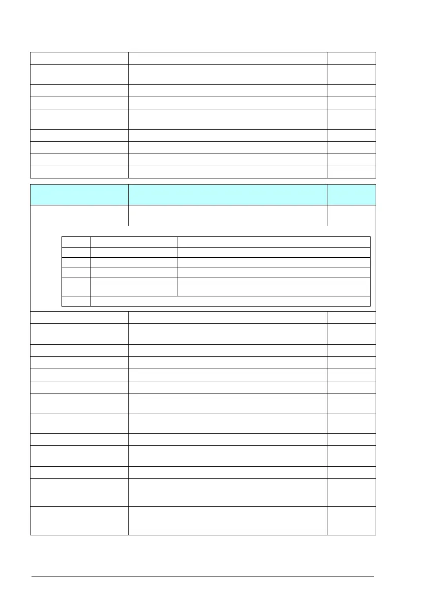
37.01 ULC output status
word
Displays the status of the monitored signal. 0b0000
0b0000…0b1111 Status of the m oni tor ed signal. 1 = 1
37.02 ULC supervision
signal
Selects the signal to be supervised. Motor
torque %
Not selected No signal selected. ULC disabled. 0
Motor speed % 01.03 Motor speed % (page 165). 1
Motor current % 01.08 Motor current % of motor nom (page 165). 2
Motor torque % 01.10 Motor torque (page 165). 3
Output power % of
motor nominal
01.15 Output power % of motor nom (page 166). 4
Output power % of
drive nominal
01.16 Output power % of drive nom (page 166). 5
Other Source selection (see Terms and abbreviations on page 162). -
37.03 ULC overload
actions
Selects an action taken if the signal stays over the overload
curve in a sector for a defined time.
Disabled
Disabled No warnings or fault generated. 0
Warning The drive generates an A8BE ULC overload warning if the
signal has been continuously over the overload curve for a
time defined by parameter 37.41 ULC overload timer.
1
Fault The drive generates a 8002 ULC overload fault if the signal
has been continuously over the overload curve for a time
defined by parameter 37.41 ULC overload timer.
2
No. Name/Value Description Def/FbEq16
Bit Name Description
0 Under load limit 1 = Signal lower than the underload curve.
1 Within load range 1 = Signal between the underload and overload curve.
2 Overload limit 1 = Signal higher than the overload curve.
3 Outside load limit 1 = Signal lower than the underload curve or higher than the
overload curve.
3…15 Reserved

 Loading...


