Parameters 179
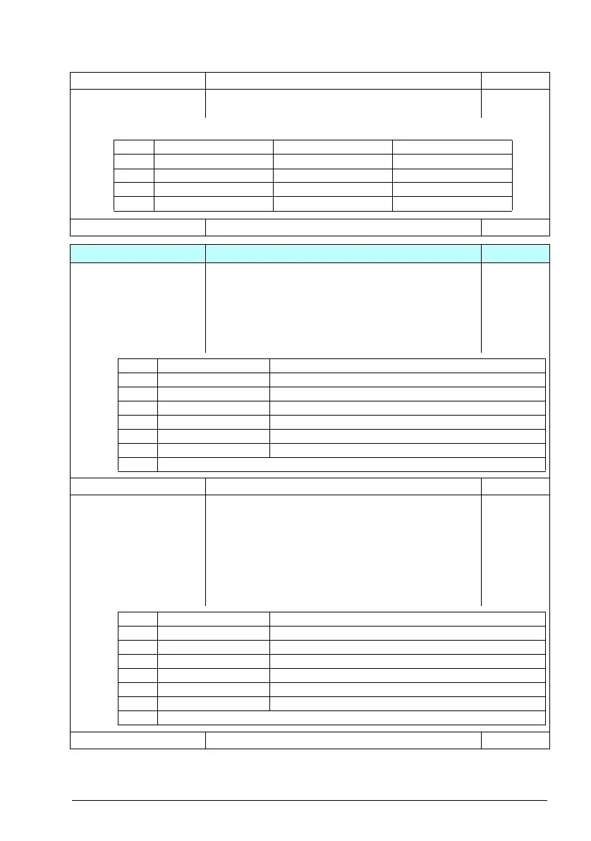
07.36 Drive configuration
2
Plug ‘n’ play configuration. Drive automatically detects and
enables any installed fieldbus or C-series option.
0x0000
0x0000...0xffff Drive configuration 2. 1 = 1
10
10 Standard DI, RO
Configuration of digital inputs and relay outputs.
10.01 DI status Displays the electrical status of digital inputs DI1...DI6. The
activation/deactivation delays of the inputs (if
any are specified) are ignored.
Bits 0…5 reflect the status of DI1…DI6.
Example: 0000000000010011b = DI5, DI2 and DI1 are on,
DI3, DI4 and DI6 are off.
This parameter is read-only.
0b0000
0b0000...0b1111 Status for digital inputs. 1 = 1
10.02 DI delayed status Displays the status of digital inputs DI1…DI6. Bits 0…5 reflect
the delayed status of DI1…DI6.
Example: 0000000000010011b = DI5, DI2 and DI1 are on,
DI3, DI4 and DI6 are off.
This word is updated only after a 2 ms activation/deactivation
delay. When the value of a digital input changes, it must
remain the same in two consecutive samples, that is for 2 ms,
for the new value to be accepted.
This parameter is read-only.
0b0000
0b0000...0b1111 Delayed statu s fo r d igital inpu ts. 1 = 1
No. Name/Value Description Def/FbEq16
Bit Name Bit Name
0 FLON-01 4 CMOD-02
1 FDNA-01 5 CPTC-02
2 FCNA-01 6 CHDI-01
3 CMOD-01 7...15 Reserved
Bit Name Description
0 DI1 1 = Digital input 1 is ON.
1 DI2 1 = Digital input 2 is ON.
2 DI3 1 = Digital input 3 is ON.
3 DI4 1 = Digital input 4 is ON.
4 DI5 1 = Digital input 5 is ON.
5 DI6 1 = Digital input 6 is ON.
6…15 Reserved
Bit Name Description
0 DI1 1 = Digital input 1 is ON.
1 DI2 1 = Digital input 2 is ON.
2 DI3 1 = Digital input 3 is ON.
3 DI4 1 = Digital input 4 is ON.
4 DI5 1 = Digital input 5 is ON.
5 DI6 1 = Digital input 6 is ON.
6…15 Reserved

 Loading...


