Parameters 345
inHg inHg 24
kCFM kCFM 25
inWC inWC 26
GPM GPM 27
gal/m gal/m 28
in wg in wg 29
MPa MPa 30
ftWC ftWC 31
76
76 PFC configuration
PFC (Pump and fan control) and Autochange configuration
parameters. See also section Pump and Fan Control (PFC)
macro on page 125.
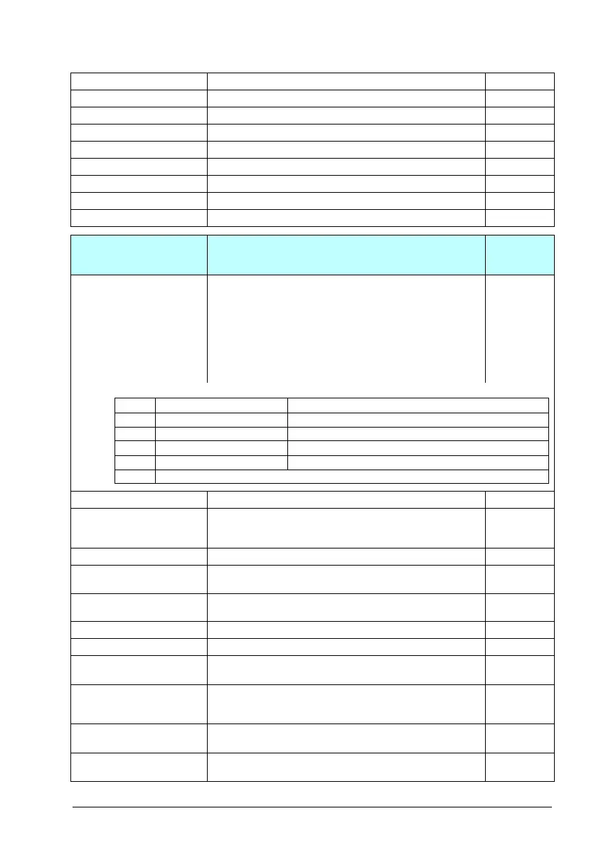
76.01 PFC status Displays the running/stopped status of the PFC motors.
PFC1, PFC2, PFC3 and PFC4 always correspond to the
1st…4th motor of the PFC system. If 76.74 Autochange
auxiliary PFC auxiliary PFC is set to Aux motors only, PFC1
represents the motor connected to the drive and PFC2 the
first auxiliary motor (the 2nd motor of the system). If 76.74 is
set to All motors, PFC1 is the first motor, PFC2 the 2nd. The
drive can be connected to any of these motors depending on
the Autochange functionality.
0b0000
0b0000…0b1111 Status of the P FC relay outpu ts. 1 = 1
76.02 PFC system status Displays the status of the PFC system in text form. Provides a
quick PFC system overview, e.g. if the parameter is added to
the Home view on the control panel.
PFC disabled
PFC disabled - 0
PFC enabled (not
started)
-1
SPFC enabled (not
started)
-2
MPFC enabled - 3
Invalid configuration - 4
PFC inactive (local
control)
-5
PFC inactive
(invalid operation
mode)
-6
Drive motor
interlocked
-7
All motors
interlocked
-8
No. Name/Value Description Def/FbEq16
Bit Name Value
0 PFC 1 running 0 = Stop, 1 = Start
1 PFC 2 running 0 = Stop, 1 = Start
2 PFC 3 running 0 = Stop, 1 = Start
3 PFC 4 running 0 = Stop, 1 = Start
4…15 Reserved

 Loading...


