R5906848 /04 DP2K SLP Series 109
5. Guide the wire of the fan through the rubber grommet (reference 7 Image 9-21) and cable clamp (reference 8
Image 9-21) and mark the wire by attaching a red colored cable tie two centimeters from the plug (reference 9
Image 9-21).
6. Install the fan assembly onto the projector chassis. Use a 3mm Allen wrench to fasten the three screws
(reference 4 Image 9-20).
7. Connect the wire of the fan with the Signal Backplane. (reference 3 Image 9-19)
9.9 Replacement of the fan of the Green channel
To access the fan of the Green channel in the Light Processor compartment the Light Processor unit
has to be removed from the projector. This procedure assumes that the Light Processor unit is
already removed from the projector.
Required tools
3mm Allen wrench.
How to replace the fan of the Green channel?
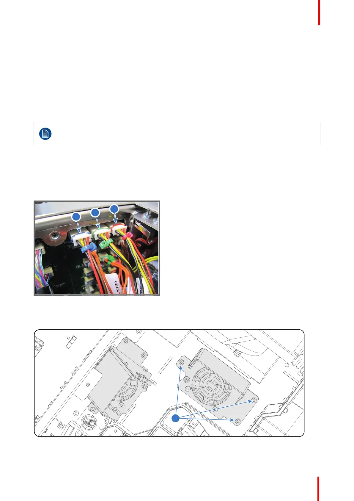
1. Disconnect the wire (reference 2 Image 9-22) of the fan from the Signal Backplane.
Image 9-22
2. Remove the fan assembly from the chassis. Use a 3mm Allen wrench to loosen the three fixation screws of
the assembly (reference 4 Image 9-23).
Image 9-23
Light Processor
 Loading...


