R5906848 /04 DP2K SLP Series266
21.1 Power Board Diagnostic LEDs in the LDM
Module
Status LED’s on the Power Board
Power boards are installed in the Laser Driver Module, at the rear of the projector.
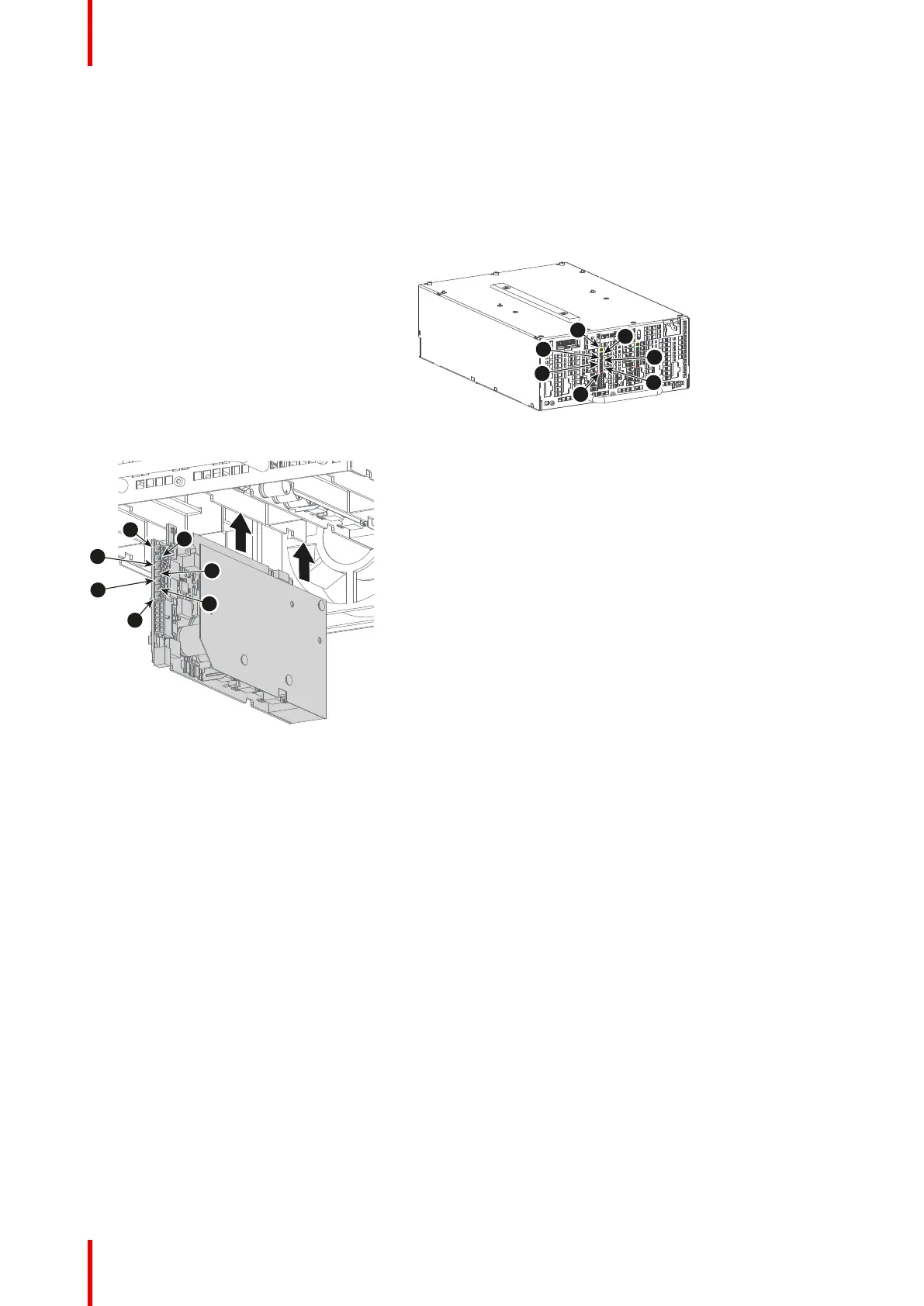
Image 21-1
Image 21-2
1 Diagnostic
LED “LDM 24V
PWR
HEARTBEAT”
(yellow)
2 Diagnostic
LED “LDM 24V
PWR Bank 3
ON” (green)
3 Diagnostic
LED “LDM 24V
PWR Bank 3
warning or
error” (red)
4 Diagnostic
LED “LDM 24V
PWR Bank 2
ON” (green)
5 Diagnostic
LED “LDM 24V
PWR Bank 2
warning or
error” (red)
6 Diagnostic
LED “LDM 24V
PWR Bank 1
ON” (green)
7 Diagnostic
LED “LDM 24V
PWR Bank 1
warning or
error” (red)
Diagnostic
Ref.
Description (LED
color)
LED Ref. Comment
1 Heartbeat (yellow) D493 0,5s on / 1,5s off when software has detected a valid hardware
configuration
2 24V supply 3 ON
(green)
D481 Lit up when 24V supply 3 is running
3 24V supply 3 warning
or error (red)
• warning: red led
on, 24V supply is
still on (green led
on)
• error: red led on,
24V supply is
turned off (green
led off)
D478 This red led is on when 1 of following parameters is out of range:
• 24V supply voltage
3 red Leds are on when :
• temperature of heatsink rectifier is high
4 24V supply 2 ON
(green)
D480 Lit up when 24V supply 2 is running
Board Diagnostic LED's
 Loading...


