R5906848 /04 DP2K SLP Series40
5.1 Introduction DP2K-SLP Series SMPS board
Introduction
The SMPS board has a separated compartment which is located below the Card Cage at the lower right side
of the projector. The SMPS compartment is air cooled by two small fans located behind the large dust filter at
the front side of the projector.
The SMPS board provides power to most of the electronic boards of the DP2K-SLP Series projector. The
SMPS board has five connectors: one to connect the mains voltage coming from the mains filter, one to
connect the PE wire, one to connect the control signals and two for the DC output voltages (connected with
the Power Backplane).
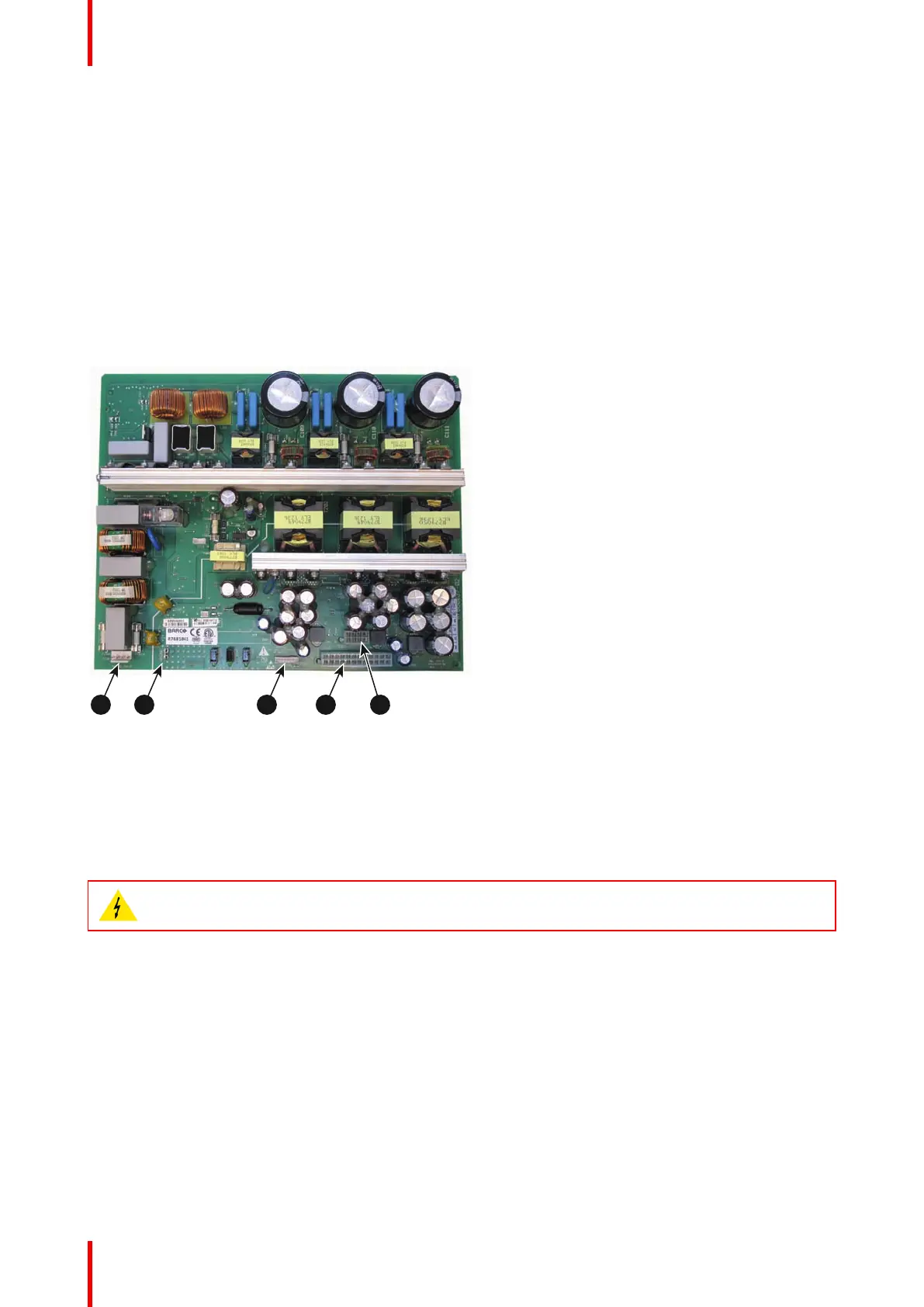
Connections
Image 5-1
1 Mains Power.
2 Protected Earth (PE).
3 Control signals.
4 DC output voltages 2 (large socket).
5 DC output voltages 1 (small socket).
5.2 Removing the SMPS board
WARNING: Disconnect the power cord of the projector from the power net and wait a few minutes
(to discharge the capacitors) prior to starting this procedure.
Required tools
3mm Allen wrench.
How to remove the SMPS board from the projector?
1. Remove the cover of the SMPS compartment. Use a 3mm Allen wrench to loosen the two screws (reference 1
Image 5-2) of the cover.
Switch Mode Power Supply (SMPS)
 Loading...


